1A More Complicated Physical Pendulum
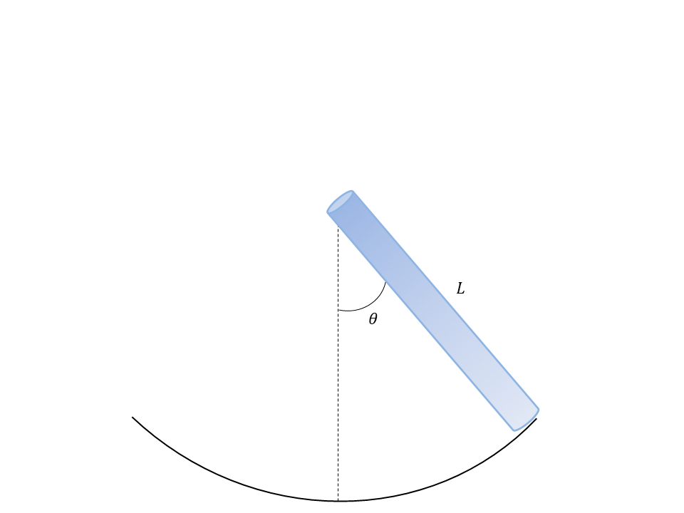
We can make a more complicated physical pendulum by assuming the mass of the leg is linearly decreasing from the hip to the foot, i.e., the leg is more massive at the hip and less massive at the foot. See Figure 1

Figure 1:A physical pendulum composed of a rod with linearly-dependent mass density.
To do this we must calculate the center of mass and the moment of inertia. Fortunately, these have very similar methods of calculation. The center of mass is calculated as
Before we assume the leg has a linear mass density decreasing from hip to foot, let’s verify that the center of mass of the uniform cylinder is . The mass distribution looks like a constant density.
where is the total mass of the leg, and is the total length of the leg. Rearranging for gives
The center of mass integral is written
Okay, the method seems to check out. For the improved model where the leg is a cylinder with linear mass distribution, we can write that linear density as
where is a constant similar to above but different (units are kg/m) for the non-uniform mass distribution. Rearranging this equation
Substituting this into Eqn. (1), we get
The moment of inertia is calculated similarly as
Using our linear mass density again, we get
Now, we can use the step time that was derived in chapter 1 on Locomotion.
We see that this step time is smaller by 25% than the uniform cylinder because the fraction in the square root goes from to .
2Fluid Friction and Viscosity
The inter-layer force proposed by Newton
describes the viscous (frictional) forces between two layers of fluid. If the layers are considered to be concentric cylinders sharing the central axis of the cylinder, we can write the area that two layers share as the surface area of a cylinder . Next, we consider the situation where this viscous force is exactly balanced by the pressure force pushing fluid down the cylinder.
where the area is now the cross-sectional (circular face) area where the fluid is being pushed into the vessel. The change is pressure comes from the fact that a pushing force is on one end of the vessel, and no force exists on the other end. This cross-sectional area is . Starting with Newton’s Second Law
In this equilibrium condition, velocity is constant, but as we’ll see the actual value of the velocity depends on the radius at which the fluid flows down the vessel. Substituting the area and moving the push force to the right hand side, we get
Let’s solve for by moving anything not involving to the right hand side.
Next, we can get the velocity at a particular r by looking at a the integral contribution over small increments, .
This gives
We know the velocity cannot be zero at , the center of the vessel. The velocity at the outside edge where , the velocity is zero, and the constant is
where is the radius of the vessel. This gives the equation (7).
From this we see that the velocity is zero at the edge of the vessel and is maximum at the center. It follows a parabolic velocity profile.