Chapter 10 - Rotational dynamics
10.1Overview
In this Chapter, we use Newton’s Second Law to develop a formalism to describe how objects rotate. In particular, we will introduce the concept of torque which plays a similar role to that of force in non-rotational dynamics. We will also introduce the concept of moment of inertia to describe how objects resist rotational motion.
10.2Rotational kinematic vectors
10.2.1Scalar rotational kinematic quantities
Recall that we can describe the motion of a particle along a circle of radius, , by using its angular position, , its angular velocity, , and its angular acceleration, . With a suitable choice of coordinate system, the angular position can be defined as the angle made by the position vector of the particles, , and the axis of a coordinate system whose origin is the centre of the circle, as shown in Figure 1.

Figure 1:Angular position for a particle moving around the axis (out of the page), along a circle of radius with a centre at the origin.}
The angular velocity, , is the rate of the change of the angular position, and the angular acceleration, , is the rate of change of the angular velocity:
If the angular acceleration is constant, then angular velocity and position as a function of time are given by:
where and are the angular position and velocity, respectively, at .
We can also describe the motion of the particle in terms of “linear” quantities (as opposed to “angular” quantities) along a one-dimensional axis that is curved along the circle. If is the distance along the circumference of the circle, measured counter-clockwise from where the circle intersects the axis, then it is related to the angular displacement:
if is expressed in radians. Similarly, the linear velocity along the axis, , and the corresponding acceleration, , are given by:
where the radius of the circle, , is a constant that can be taken out of the time derivatives. For motion along a circle, the velocity vector, , of the particle is always tangent to the circle (), so corresponds to the speed of the particle. The acceleration vector, , is in general not tangent to the circle; represents the component of the acceleration vector that is tangent to the circle. If , then , and the particle is moving with a constant speed (uniform circular motion), and the acceleration vector points towards the centre of the circle.
10.2.2Vector rotational kinematic quantities
In the previous section, we defined angular quantities to describe the motion of a particle about the axis along a circle of radius that lies in the plane. By using vectors, we can define the angular quantities for rotation about an axis that can point in any direction. Given an axis of rotation, the path of any particle rotating about that axis can be described by a circle that lies in the plane perpendicular to that axis of rotation, as illustrated in Figure 3.
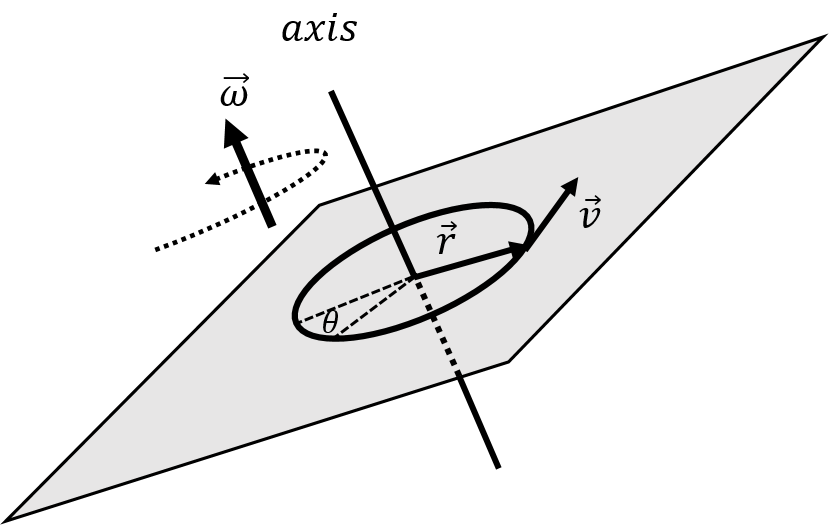
Figure 3:Defining the vector and the angular velocity, for a particle with velocity rotating about an axis in a general direction.
We define the vector, , for a particle to be the vector that goes from the axis of rotation to the particle and is in a plane perpendicular to the axis of rotation, as in Figure 3. Given the velocity vector of the particle, , we define its angular velocity vector, , about the axis of rotation, as:
The angular velocity vector is perpendicular to both the velocity vector and the vector , since it is defined as their cross-product. Thus, the angular velocity vector is co-linear with the axis of rotation. By using the angular velocity vector, we can specify the direction of the axis of rotation as well as the direction in which the particle is rotating about that axis. The direction of rotation is given by the right hand rule for axial vectors: when you point your thumb in the same direction as the angular velocity vector, the direction of rotation is the direction that your fingers point when you curl them, as illustrated in Figure 4.

Figure 4:Using the right hand rule for axial vectors. In this case, the direction of rotation is counter clockwise when looking at the page (the direction that the fingers curl), so the rotation vector points out of the page (the direction of the thumb).
This definition of the angular velocity is consistent with the description from the previous section for motion about a circle of radius that lies in the plane, as in Figure 1. In that case, the magnitude of the angular velocity is given by:
where is the angle between the vectors and ( for motion around a circle). The direction of the angular velocity in Figure 1 is in the positive direction, which corresponds to counter-clockwise rotation about the axis.
One can always define an angular velocity vector relative to a point of rotation, even if the particle is not moving along a circle. If we define the vector to be the vector from the point of rotation to the particle, then the angular velocity vector describes the motion of the particle as if it were instantaneously moving in a circle centred at the point of rotation, in a plane given by the vectors and .
Consider, for example, the particle in Figure 5 which is moving in a straight line with a velocity vector in the plane at a position relative to the origin. We can define its angular velocity vector relative to the origin, which will be in the positive direction.

Figure 5:Angular position for a particle moving in a straight line.
The angular velocity describes the motion of the particle as if it were instantaneously moving along a circle of radius centred about the origin. The angular velocity is related to the component of , , that is perpendicular to (which is the component tangent to the circle of radius , in Figure 5:
where is the angle between and .
Similarly, we can define the angular acceleration vector, , about an axis of rotation:
where is the particle’s acceleration vector, and is the vector from the axis of rotation to the particle. The direction of the angular acceleration is co-linear with the axis of rotation and the right-hand rule gives the rotational direction of the angular acceleration. We can also define the angular acceleration about a point; in that case, the direction of the vector will define an instantaneous axis of rotation about a circle of radius centred at the point as well as the direction of the angular acceleration about that axis.
Finally, we can define an angular displacement vector, , relative to an axis of rotation. The direction of the angular displacement vector will be co-linear with the axis of rotation, its direction will indicate the direction of rotation about that axis, and its magnitude (in radians) will correspond to the angular displacement (as shown in Figure 3). We can only relate the angular displacement vector to an infinitesimal linear displacement vector, , since the position vector from the axis of rotation will be different at each end of the displacement vector if the displacement is large. The infinitesimal angular displacement vector that corresponds to an infinitesimal displacement vector, , is defined as:
The instantaneous angular velocity vector is the rate of change of the angular displacement vector:
where is the (instantaneous) tangential velocity around the circle (i.e. the component of the velocity that is perpendicular to ). The angular acceleration vector is the rate of change of the angular velocity vector:
Given the angular kinematic quantities, the related linear quantities at a position from the axis of rotation are given by:
where the linear quantities are always in the direction perpendicular to (tangent to the circle, for motion around a circle). In other words, one cannot, say, take the acceleration vector, obtain the angular acceleration vector, and then get back the original acceleration vector - one will only get back the component of the acceleration vector that is perpendicular to .
10.3Rotational dynamics for a single particle}
Suppose that a single force, , is acting on a particle of mass . Newton’s Second Law for the particle is then given by:
We can define a point of rotation such that is the position of the particle relative to that point. We can take the cross-product of with both sides of the equation in Newton’s Second Law:
The left hand-side of the equation is called “the torque of relative to the point of rotation”, and is usually denoted by :
The right-hand side of the equation is related to the angular acceleration vector, , about that point of rotation:
Putting this altogether, we get:
If more than one force is exerted on the particle, it is easy to show that the net torque from the net force on the particle is equal to the sum of the torques on the particle:
We can write “Newton’s Second Law for the rotational dynamics of a particle”:
This equation provides us an alternate formulation to Newton’s Second Law that is useful for describing the motion of a particle that is rotating. The left-hand side of the equation corresponds to the “causes of motion” (much like the sum of the forces in Newton’s Second Law), and the right-hand side of the equation to the inertia and the kinematics. A few things to note when comparing to Newton’s Second Law:
The rotational quantities, torque and angular acceleration, are only defined with respect to a point or axis of rotation (as this determines the vector ). If one chooses a different point of rotation, then the torque and angular acceleration will be different.
The angular acceleration of a particle is proportional to the net torque exerted on it, much like the linear acceleration is proportional to the net force exerted on the particle.
Torque about a centre of rotation can be thought of as the equivalent of a force that causes things rotate about an axis that goes through the point of rotation and that is parallel to the torque/angular acceleration vectors.
Instead of mass, it is mass times that plays the role of inertia and determines how large of an angular acceleration a particle will experience for a given net torque.
10.4Torque
The torque associated with a force is a mathematical tool to describe how much a particular force will cause a particle (or solid) object to rotate about a given point or a given axis of rotation. A torque is only defined relative to an axis or point of rotation. It never makes sense to say “the torque is ...”, and one should always say "the torque about this axis/point of rotation is ... ". Angular quantities (torque, angular velocity, angular displacement, etc) are only ever defined relative to a specific axis or point of rotation.
Mathematically, the torque vector from a force, , exerted at a position, , relative to the axis or point of rotation is defined as:
Note that the torque from a given force increases if that force is further from the axis of rotation (if has a bigger magnitude).
Consider the solid disk of radius, , depicted in Figure 9. The disk can rotate about an axis that passes through the centre of the disk and that is perpendicular to the plane of the disk. A force, , is exerted on the edge of the disk as shown.
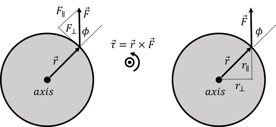
Figure 9:A force exerted on the perimeter of a disk that can rotate about an axis that is perpendicular to the disk and that passes through its centre. We can determine the resulting torque by considering either the component of that is perpendicular to (left panel) or the component of that is perpendicular to (right panel). The torque vector, , is out of the page, as illustrated in the centre.
Intuitively, that force will cause the disk to rotate in the counter-clockwise direction. The torque from the force about the axis as rotation is given by:
where the vector is perpendicular to the axis of rotation and goes from the axis of rotation to the point where is exerted. The direction of the torque vector is out of the page (right hand rule, see Figure 9), and will thus lead to an angular acceleration that is also out of the page, which corresponds to the counter-clockwise direction, as anticipated.
We can break up the force into components that are parallel () and perpendicular () to the vector , as shown on the left panel of Figure 9. Only the component of the force that is perpendicular to will contribute to rotating the disk. Imagine that the force is from a string that you have attached to the perimeter of the disk; if you pull on the string such that the force is parallel to , the disk would not rotate. The magnitude of the torque is given by:
where is the angle between and , as shown in Figure 9. is precisely the component of that is perpendicular to , so we could also write the magnitude of the torque as:
which highlights that only the component of the force that is perpendicular to contributes to the torque. Instead of combining the with to obtain , the component of perpendicular to , we can instead combine the with in Equation (28) to obtain , the component of that is perpendicular to . This is illustrated in the right panel of Figure 9. The magnitude of the torque is thus also given by:
The quantity is called the “lever arm” of the force about a specific axis of rotation.
10.5Rotation about an axis versus rotation about a point
When defining angular quantities (torque, angular acceleration, etc.), it is important to identify whether these are defined relative to an axis or to a point of rotation. This, in turn, determines the vector that is involved in the definition of the angular quantities.
Consider a disk of radius with a force, exerted on its perimeter, as illustrated in Figure 10. The disk can only rotate about an axis that is perpendicular to the disk and that goes through the centre of the disk, like a wheel mounted on an axle. The force has a component, , that lies in the plane perpendicular to the axis of rotation, and a component, , that is parallel to axis of rotation.
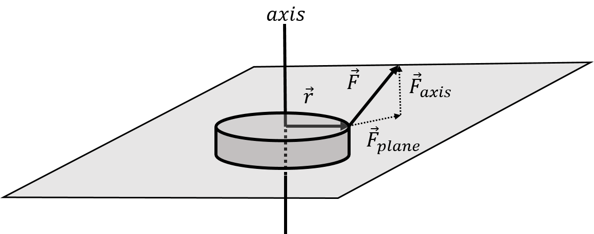
Figure 10:A force exerted on disk that can only rotate about an axis through its centre and perpendicular to its plane. Only the component of that is in the plane perpendicular to the axis of rotation, , will contribute to the torque about the axis of rotation.
The vector is ** always defined to be perpendicular to the axis of rotation and to go from the axis of rotation to the point where the force is exerted**, as illustrated. The torque obtained by taking the cross product:
will be perpendicular to both and , and will thus not be parallel to the axis of rotation. Only the component of the torque that is parallel to the axis of rotation will contribute to rotating the disk about the axis. Only the component of the force that lies in the plane perpendicular to the axis of rotation, , will contribute to the component of the torque about that axis of rotation. Thus, when we need to determine the torque about an axis of rotation, we can consider vectors and that lie in the plane perpendicular to the axis of rotation. The torque of relative to the axis of rotation is thus:
Furthermore, only the component of that is perpendicular to will contribute to that torque, as we saw in the previous section.
In general, solid objects such as a disk can only rotate about an axis. In that case, one can consider only the components of forces that lie in the plane perpendicular to the axis of rotation in order to calculate the components of the torques about that axis that are parallel to that axis.
A point particle may be able to rotate about any axis that goes through a point of rotation. The net torque vector on the particle about that point will indicate the direction of the axis about which the particle would rotate. This is illustrated in the left panel of Figure 11.
Instead, if the particle were constrained to rotate about the axis (e.g. if the particle is on a track), then we would use the component of the torque vector that is parallel to the axis to describe its motion, as illustrated in the right panel. The component of the torque could be determined by using only the components of the forces that lie in the plane perpendicular to the axis, and defining the vector from the axis to the particle rather than from the point of rotation to the particle.

Figure 11:Left panel: a particle rotating about a circle centred at the origin with an axis determined from the net torque vector. Right panel: a particle that is constrained to rotate about the axis.
10.6Rotational dynamics for a solid object
We now consider the rotational dynamics for a solid object about a specific axis of rotation. Just as we did in Chapter 10, we model a solid object as a system made of many particles of mass . Because all of the points in a solid must move in unison, they all rotate about an axis of rotation instead of a point. We describe the position of each particle by a vector that is perpendicular to the axis of rotation and goes from the axis to the corresponding particle, as shown in Figure 12.
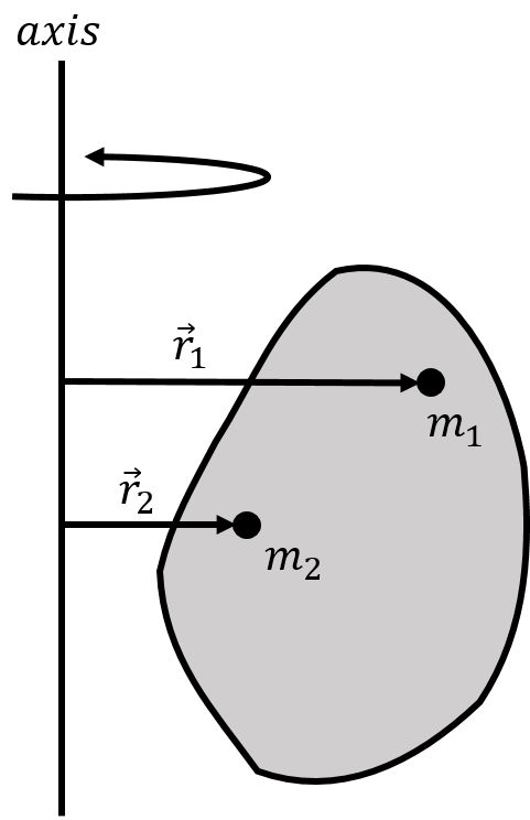
Figure 12:Two point particles that are part of a large solid object and their position vectors relative to an axis of rotation.
We wish to model the motion of the object as it rotates about a specific axis. Thus, when considering the net torque on any particle , we only consider the component of the particle’s net torque that is parallel to the axis of rotation (that component of torque that comes from forces that are in the plane perpendicular to the rotation axis).
We can write the rotational version of Newton’s Second Law for particle, , with mass , and position vector relative to the rotation axis:
where is the -th torque on particle . is the net torque on the particle about the axis of rotation and is the particle’s angular acceleration about that axis.
We can divide the torques exerted on a particle into internal and external torques. Internal torques are those exerted by another particle in the system, whereas external torques are exerted by something external to the system. If particle 1 exerts a torque on particle 2, particle 2 will exert an equal and opposite torque, on particle 1.
Indeed, consider the two particles that exert an equal and opposite force (Newton’s Third Law), , on each other, and an arbitrary point/axis of rotation, as illustrated in Figure 13. The torque on particle 1 from the force exerted by particle 2 will have the same magnitude as the torque on particle 2 from the force by particle 1. This is because both forces have the same magnitude and they are co-linear, which results in them having the same lever arm. The torque vector from each force will be in opposite directions, because the forces are in opposite direction. Newton’s Third Law thus also holds for torques.

Figure 13:Two particles will exert equal and opposite torques on each other due to Newton’s Third Law; the forces exerted by each particle on the other are co-linear and will thus have the same lever arm relative to any point/axis of rotation.
We can sum together the equations for each particle :
where the sum over all of the torques exerted on each particle will be equal to the net external torque exerted on all of the particles, since the sum of the internal torques, , will be zero:
where is the net external torque on the system.
All of the particles are part of the same rigid body, and cannot move relative to each other. Furthermore, they must all move around circles that are centred about the axis of rotation and in a plane perpendicular to that axis. They must thus all have the same angular acceleration[25], . We can thus factor the angular acceleration, , out of the sum.
We can thus write Newton’s Second Law for rotational dynamics of a solid object as:
The term in parentheses describes how the various masses are distributed relative to the axis of rotation. The term in parenthesis is called the moment of inertia of the object, and usually denoted with the letter, :
The moment of inertia is a property of the object relative to a specific axis of rotation. Re-writing Newton’s Second Law for the rotational dynamics of solid objects using the moment of inertia:
The net torque exerted on an object in the direction of the axis of rotation is thus equal to its moment of inertia about that axis multiplied by its angular acceleration about that axis. In other words, the moment of inertia describes how the object will resist rotational motion given a net torque. An object with a smaller moment of inertia will have a larger angular acceleration for a given torque. Again, this is analogous to the linear case, where the acceleration of an object given a net force is determined by its inertial mass. ex:rotationaldynamics:dumbbell_2m)=
10.7Moment of inertia
In order to model how an object rotates about an axis, we use Newton’s Second Law for rotational dynamics:
where is the net external torque exerted on the object about the axis of rotation, is the angular acceleration of the object, and is the moment of inertia of the object (about the axis). If we consider the object as being made of many particles of mass each located at a position relative to the axis of rotation, the moment of inertia is defined as:
Consider, for example, the moment of inertia of a uniform rod of mass and length that is rotated about an axis perpendicular to the rod that pass through one of the ends of the rod, as depicted in Figure 17.

Figure 17:A rod of length and mass being rotated about an axis perpendicular to the rod that goes through one of its ends.
We introduce the linear mass density of the rod, , as the mass per unit length:
We model the rod as being made of many small mass elements of mass , of length , at a location , as illustrated in Figure 17. Using the linear mass density, the mass element, , has a mass of:
The rod is made of many such mass elements, and the moment of inertia of the rod is thus given by:
If we take the limit in which the length of the mass element is infinitesimally small () the sum can be written as an integral over the dimension of the rod:
where we re-expressed the linear mass density in terms of the mass and length of the rod. In general, we can write the moment of inertia of a continuous object as:
where is a small mass element that makes up the object, is the distance from that mass element to the axis of rotation, and the integral is over the dimension of the object. As we did above, we would usually set up this integral so that is expressed in terms of so that we can take an integral over .
10.7.1The parallel axis theorem
The moment of inertia of a solid object can be difficult to calculate, especially if the object is not symmetric. The parallel axis theorem allows us to determine the moment of inertia of an object about an axis, if we already know the moment of inertia of the object about an axis that is parallel and goes through the centre of mass of the object.
Consider an object for which we know the moment of inertia, , about an axis that goes through the object’s centre of mass. We define a coordinate system such that the origin is located at the centre of mass, and the axis is parallel to the axis about which we know the moment of inertia, as illustrated in Figure 19.
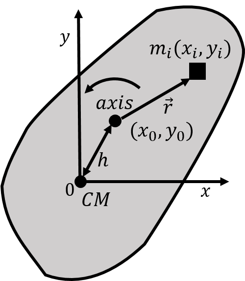
Figure 19:An object with a coordinate system whose origin is at the object’s centre of mass, and for which we know the moment of inertia about the axis. We wish to determine the object’s moment of inertia through a second axis, parallel to the axis, but located a distance away from the centre of mass.
We wish to determine the moment of inertia for the object for an axis that is parallel to the axis, but goes through a point with coordinates located a distance away from the centre of mass. The moment of inertia about an axis parallel to the axis and that goes through that point, is given by:
where is a mass element of the object located at a distance from the axis of rotation. If the mass element is located at a position relative to the centre of mass, we can write the distance in terms of the position of the mass element, and of the position of the axis of rotation:
Note that:
The moment of inertia, , can thus be written as:
where we broke the sum up into several sums, and factored constant terms (, , ) out of the sums, since these constants do not depend on which mass element we are considering. The first term is the moment of inertia about the centre of mass, since is the distance to the centre of mass. The second term is times the total mass of the object, since the sum of all the is just the mass, , of the object. Now consider the term:
The sum, is the numerator in the definition of the coordinate of the centre of mass! The sum is thus zero, because we choose the origin to be located at the centre of mass. The last two terms in the sum are thus identically zero, because they correspond to the and coordinates of the centre of mass!
We can thus write the parallel axis theorem:
where is the moment of inertia of an object of mass about an axis that goes through the centre of mass and, , is the moment of inertia about a second axis that is parallel to the first and a distance away.
10.8Equilibrium
In this section, we consider the conditions under which an object is in static or dynamic equilibrium. An object is in equilibrium if it does not rotate when viewed in a frame of reference where the object’s centre of mass is stationary (or moving at constant velocity).
10.8.1Static equilibrium
An object is in static equilibrium, if both the sum of the external forces exerted on the object and the sum of the external torques (about any axis) are zero. If the object is in static equilibrium the centre of mass will have no acceleration and the object will have no angular acceleration. In the centre of mass frame of reference, the object is immobile.
10.8.2Dynamic equilibrium
When an object is in dynamic equilibrium, its centre of mass is accelerating, but the object is not rotating when viewed from its centre of mass frame of reference. Thus, the sum of the external forces exerted on the object is not zero, while the net external torque exerted on the object is zero, in the frame of reference of the centre of mass.
Consider, for example, a speed skater going around a circular track of radius , and leaning into the centre making an angle with the ice, as depicted in Figure 22. The skater’s centre of mass is accelerating, because she is going around a circle, so the net force on the skater is not zero. However, in the reference frame of the skater, the skater is not rotating; she is thus in dynamic equilibrium.
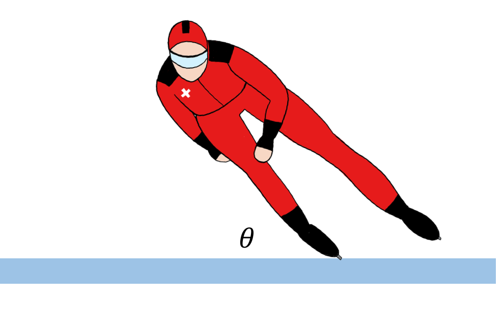
Figure 22:A speed skater leaning in as she goes around a circle.
The forces on the skater are:
, her weight, exerted at her centre of mass with magnitude, .
, a normal force, exerted by the ice upwards on her skates.
, a force of static friction, exerted towards the centre of the circle, by the ice on her skates.
The forces are illustrated in Figure 23 along with our choice of coordinate system.
.](/PhysicsArtOfModeling/build/skater_fbd-bd275b6ef661490b6c1cbe995c321444.png)
Figure 23:Forces on the speed skater from Figure 22.
The sum of the forces exerted on the skater must be towards the centre of the circle and equal to the mass of the skater times her centripetal acceleration (which is the acceleration of her centre of mass, ). The and components of Newton’s Second Law are thus given by:
All of the forces exerted on the skater are in the plane, so we consider torques about an axis that is co-linear with the axis. Consider the torques about an axis through the point of contact between the skates and the ice; there is a net torque in the counter-clockwise direction due to the weight of the skater (the weight is the only force that can result in a torque about the point of contact with the ice). We expect that the skater would topple over, however, this must not be a correct model for the skater, since we know that it is possible for her to lean in without falling.
Consider, instead, the sum of the torques about an axis through her centre of mass. If the skater has a length and the centre of mass is in the middle of the skater, the sum of the torques about the centre of mass is given by the torques from the normal forces and the force of friction:
About the centre of mass, the torques must be zero for the skater not to rotate, and this would give a relation between the force of static friction and the normal force.
Why do we get an incorrect model when we take the torques about the point of contact between the ice and the skater? In order to determine if the skater is rotating, we need to be in the same reference frame as the skater. However, the frame of reference of the skater is not an inertial frame of reference, since the skater is accelerating. We can still model the forces on the skater in the non-accelerating frame of reference, as long as we include the inertial force, , in that frame of reference. In the frame of reference of the skater, there is an additional inertial force, , in order for the sum of the forces to be zero (in the frame of reference of the skater, the sum of the forces must be zero since the skater is not accelerating in that frame of reference). The additional inertial force is exerted at the centre of mass, as illustrated in Figure 24.
 as seen in the accelerating frame of reference of the centre of mass.](/PhysicsArtOfModeling/build/skater_fbdcm-7f795d7a920f22b5b6661371d50d145f.png)
Figure 24:Forces on the speed skater from Figure 22 as seen in the accelerating frame of reference of the centre of mass.
The reason that our model worked when taking the torques about the centre of mass is that the inertial force, exerted at the centre of mass, does not result in a torque (since it has a lever arm of zero). Our model was technically wrong, but if we take the torques about the centre of mass, then we do not need to worry about the inertial force. If we include the additional inertial force, then we can take the torques about any point, just as in the static equilibrium case.
10.9Summary
We can describe the kinematics of rotational motion using vectors to indicate both an axis of rotation and the direction of rotation about that axis. If a particle with velocity vector, , is rotating in an circle about an axis, then its angular velocity vector, , relative to that axis is defined as:
where is a vector from the axis of rotation to the particle. The particle rotates in a circle that lies in the plane defined by and , perpendicular to the axis of rotation. The direction of the angular velocity vector is co-linear with the axis of rotation and the direction of rotation is given by the right-hand rule for axial vectors.
One can define the angular velocity of a particle relative to a point of rotation, even if the particle is not moving in a circle. In that case, the angular velocity corresponds to the angular velocity of the particle as if it were instantaneously moving about a circle.
If a particle moving around a circle has a tangential acceleration, , then its angular acceleration vector is defined as:
The torque from a force, , exerted at a position , relative to an axis (or point) of rotation is defined as:
Torque is analogous to force in that it is used to model the causes of motion. Torques are only ever defined relative to an axis or point of rotation. The torque vector will be co-linear with the axis about which the object on which the force is exerted would rotate as a result of that force.
The magnitude of the torque can be written using either the component of the force, perpendicular to the vector , or the lever arm, , of the force relative to the axis of rotation:
where is the angle between the vectors and when these are placed ``tail to tail’'.
Using rotational/angular quantities, we can modify Newton’s Second Law to describe rotational dynamics about a given axis (or point) of rotation. For a point particle, this gives:
where is the net torque on the particle (the sum of the torques from each force exerted on the particle) about the axis, and is the resulting angular acceleration about that axis.
For an object (either continuous or made of point particles), the rotational version of Newton’s Second Law for rotation about a specific axis is given by:
where is the moment of inertia of the object about that axis.
The moment of inertia of an object about an axis of rotation is given by
if the object is modelled as a system of point particles of mass each a distance from the axis of rotation. For a continuous object, the moment of inertia is given by:
where is a small mass element a distance from the axis of rotation and the integral is over the dimension of the object. Generally, one can set up the integral by expressing in terms of using the density of the object, and then integrating over the dimension of the object.
If the moment of inertia of an object of mass about an axis that goes through the centre of mass is given by , then the moment of inertia, , of the object through an axis that is parallel and a distance from the centre of mass is given by the parallel axis theorem:
Objects are in equilibrium if they are not rotating when viewed in their centre of mass frame of reference. Thus, for an object to be in equilibrium, the sum of the torques on the object, in the centre of mass reference frame, must be zero.
An object is in static equilibrium if the centre of mass is not accelerating, and thus the sum of the external forces on the object is zero. To model the torques on an object in static equilibrium, one can choose the axis about which to calculate the torques. A good choice is to choose an axis that is perpendicular to the plane in which the forces on the object are exerted (if such a plane exists), and to choose the axis to go through a point where at least one force is exerted (so that torques exerted at that point are identically zero).
An object is in dynamic equilibrium if the centre of mass is accelerating, but the object does not rotate when viewed in the frame of reference of its centre of mass. In dynamic equilibrium, if one models the torques exerted on the object about an axis that does not go through the centre of mass, then one must remember to include an inertial force exerted at the centre of mass.
10.10Thinking about the material
10.11Sample problems and solutions
10.11.1Problems
10.11.2Solutions
Solution 10.1
We need to split up the disk into mass elements, , that we can sum together to obtain the moment of inertia of the disk. We can choose a ring of radius and radial thickness for the shape of our mass element, as depicted in Figure 26.
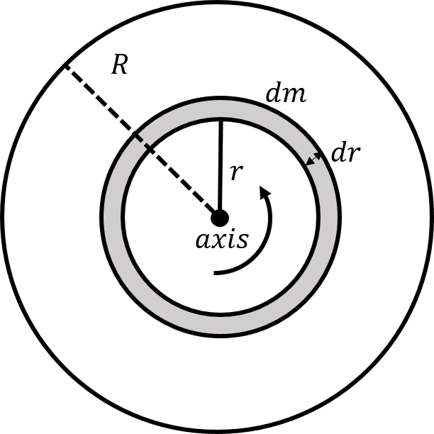
Figure 26:A mass element, , in the shape of a ring of radius and radial thickness .
We can define a surface mass density, , equal to the mass per unit area of the disk:
The mass of the ring shaped element is thus given by:
where is the area of the mass element. You can imagine unfolding the mass element into a rectangle of height and of length to obtain its area. Now that we have expressed the mass element in terms of , we can proceed to calculate the moment of inertia of the disk.
We know from the Example 10.4, that the infinitesimal moment of inertia, , of a ring of radius and infinitesimal mass, , about its axis of symmetry is given by:
The moment of inertia of the disk, is found by summing the moments of inertia of the infinitesimal rings:
where we removed the surface mass density by expressing it in term of the total mass and radius of the disk.
Discussion: The moment of inertia of a disk of mass and radius is half of that of a ring of radius and mass . It is thus easier to rotate the disk than the ring.
Solution 10.2
The whole system does not move and so it is in static equilibrium. In order to determine the forces exerted on the bar by the rope and the hinge, we model the bar as being in static equilibrium. The forces exerted on the bar are:
, the weight of the bar, with magnitude , exerted at the bar’s centre of mass.
, a downwards forced exerted by the sign at the end of the bar, with magnitude .
, a force of tension exerted by the rope at a distance from the wall.
, a force exerted by the hinge on the bar at the end next to the wall[26]. We expect that the force from the hinge will have both a horizontal component, , and a vertical component, , in order for the net force on the bar to be zero.
The forces are illustrated in Figure 27 along with our choice of coordinate system (and the axis, not shown, points out of the page).

Figure 27:Forces on the bar that is holding the sign of mass .
We start by writing out the and components of Newton’s Second Law (with zero acceleration):
We can choose the axis about which to calculate the torques. Since all of the forces are in the plane, we choose to calculate the torques about an axis parallel to the axis that goes through the hinge on the wall. The force from the hinge, , will thus result in a torque of zero (since it has a lever arm of zero). The torque from each force about the hinge is given by:
The sum of the torques in the direction must be zero for static equilibrium, which allows us to determine the magnitude of the force of tension:
Using the and components of Newton’s Second Law, we can now use the tension to determine the and components of the force exerted by the hinge:
We find that the component of the force from the hinge could be in the positive or negative direction, depending on the sign of . In particular, if , then the force exerted by the hinge, , has a component in the positive direction, as illustrated in Figure 27. However, if , then the hinge exerts a force that has a negative component in the direction, unlike that illustrated in the Figure.
Discussion: In this example, we saw that we needed to use both the sum of the forces and the sum of the torques in order to determine the forces on the bar.