Chapter 19 - Electric circuits
19.1Overview
In this chapter, we develop the tools to model electric circuits. This will allow us to determine the current and voltages across different components, such as resistors and capacitors, within a circuit. We will also discuss how a battery can provide a current at a fixed potential difference, and how one can construct devices to measure current and voltages.
19.2Batteries and simple circuits
:label: sec:circuits:batteries A battery is an electric component that provides a constant electric potential difference (a fixed voltage) across its terminals. Luigi Galvani was the first to realize that certain combinations of metals placed into contact with each other can lead to an electric potential difference (or rather, he realized that they can make the legs of a dead frog twitch, which we now understand to be from the potential difference due to the metals). Effectively, Galvani created the first “electrochemical cell”. Alessandro Volta then combined several of these cells together to form the “voltaic pile”, which is what we would now call a battery (a battery is technically a combination of several cells, or a “battery of cells”, although one often uses the term battery even if only a single electric cell is involved).
19.2.1The electrochemical cell
An electric cell can be constructed from metals that have different affinities to be dissolved in acid. A simple cell, similar to that originally made by Volta, is comprised of two metal electrodes placed in a liquid called electrolyte, as illustrated in Figure 1. Common materials used are carbon (Volta used silver) and zinc for the electrodes, and sulfuric acid for the electrolyte. Before the cell is constructed, the electrodes and the electrolyte are all electrically neutral.
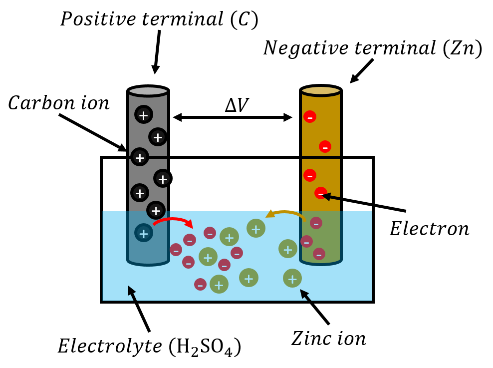
Figure 1:A simple electric cell, where zinc ions dissolve in sulfuric acid leaving electrons on the metal.
Once the zinc is immersed in the electrolyte, the zinc atoms tend to dissolve into the electrolyte in the form of zinc ions (doubly charged, Zn). This leaves an excess of electrons on the zinc electrode, resulting in a net negative electric charge. Similarly, the positively charged zinc ions attract electrons from the carbon electrode into the solution, leaving the carbon electrode positively charged. Very quickly, an equilibrium is reached, since at some point, the negative charge of the zinc electrode will electrically attract positive zinc ions, preventing any more zinc ions from dissolving into the solution. Similarly, as the carbon electrode builds a positive charge, that charge will eventually prevent electrons from “jumping” into the solution. At this point, there will be a fixed electric potential difference between the two electrodes (terminals) of the battery.
If the two electrodes are connected together through a resistor, the electrons will leave the zinc electrode, cross the resistor, and end up on the positive carbon electrode. This will leave space for more electrons on the zinc electrode, so more zinc ions will dissolve into the solution. Thus, a circuit is formed, where electron travel up the zinc electrode, through the resistor and back down the carbon electrode. At the same time, more and more zinc ions dissolve into the electrolyte, until the zinc electrode is completely dissolved. In practice, the zinc ions travel through the solution and plate onto the carbon electrode (the electrons do not quite “jump” into the electrolyte, rather, it is the zinc ions that move in the electrolyte). Since the charge on the electrodes is continuously replenished, the potential difference between the electrodes remains constant even as current is flowing.
The electric cell will stop working once the zinc electrode has completely dissolved (this is what happens when your battery is dead). Note that there is also a maximum current that the cell can supply, which depends on the rate at which the zinc can dissolve into the electrolyte and plate onto the carbon electrode. If the electrodes of the cell are connected with a very low resistance resistor, the resulting current will be too large for the potential difference to be maintained. Most electric cells work in similar ways, although the chemical reactions can be much more complex. Sometimes, the chemical reaction is reversible; one could use a different battery to apply a negative voltage to the carbon electrode to reverse the reaction and plate the zinc back onto the zinc electrode, thus “recharging the battery” (and converting electric energy back into stored chemical potential energy).
19.2.2The ideal battery in a circuit
As we proceed, we will use the term “battery” loosely to refer to a device (such as an electric cell or collection of cells) that can provide a fixed potential difference between two terminals (or electrodes). Figure 2 shows the circuit diagram for a battery, consisting of two (or four) vertical bars, with the larger bar indicating the positive terminal of the battery.
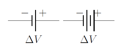
Figure 2:Circuit diagram symbols that can be used for a battery.
Figure 3 shows the circuit diagram symbols that are used for a resistor (different symbols are used in North American and in Europe).

Figure 3:Circuit diagram symbols for a resistor, using the North American convention (left), and the European convention (right).
Figure 4 shows a circuit diagram for a very simple circuit consisting of a single battery connected to a resistor. When drawing a circuit diagram (or making a real circuit), one connects the various components together (e.g. batteries and resistors) with segments of wire that have zero resistance, even if, in practice, wires always have some resistance. However, since the wires are connected in series with resistors (or other components that have a resistance), one can always include the resistance of the wires by adding it to the resistance of the other components. For example, in Figure 4, if the wires have a total resistance of , we could simply model the circuit as if the resistor had a resistance of instead of . In practice, this is usually accounted for when a circuit diagram is made (i.e. any resistors include the resistance of the wires connected to it).
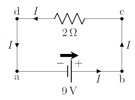
Figure 4:A simple circuit, showing a battery and a resistor. For ease in analyzing circuits, we suggest drawing a ``battery arrow" above batteries that goes from the negative to the positive terminal.
The circuit in Figure 4 is simple to analyze. In this case, whichever charges exit one terminal of the battery must pass through the resistor and then enter the other terminal of the battery. We always use conventional current to analyze a circuit. Thus, we model the circuit as if positive charges exit the positive terminal of the battery, go through the resistor, and then enter the negative terminal of the battery.
We recommend that you always draw a “battery arrow” for each battery in a circuit diagram to indicate the direction in which the electric potential increases and in which direction the conventional current would exit the battery if a simple resistor were connected across the battery. We also indicate the current that is flowing in any wire of the circuit by drawing an arrow in the direction of current on that wire (labelled in Figure 4).
It is helpful to think about the value of the electric potential along different parts of a circuit. Below (Figure 5), we have taken the circuit from Figure 4 and highlighted regions where the electric potential is constant.
 showing the two regions over which the electric potential is constant.](/PhysicsArtOfModeling/build/batteryresistor_colo-caab9ca3e130f4b4b3c9d44868f7d464.png)
Figure 5:The same circuit as in Figure 4 showing the two regions over which the electric potential is constant.
Since the wires have no resistance, the electric potential is constant along a wire. In other words, because the wire has no resistance, the charges/current cannot dissipate any power in the wire (), and the charges do not “lose” any potential energy (and so the potential cannot change). The only place where the charges can dissipate energy is inside the resistor. Once the charges have crossed the resistor, the electric potential in the wire is again constant until they reach the other terminal of the battery. Thus, in this simple circuit, the electric potential difference across the resistor is the same as the potential difference across the terminals of the battery. This is shown by the coloured areas in Figure 5. If we choose to be defined at the negative terminal of the battery, then the potential is everywhere in the red area (to the right of the resistor), and everywhere in the grey area (to the left of the resistor).
We can apply Ohm’s Law (the macroscopic version) to the resistor and determine the current in the circuit, since we know the potential difference across the resistor:
It is helpful to think of circuits in terms of energy. Charges move along the circuit and their potential energy changes as they go through components, while it remains constant as they move through a wire. If a positive charge enters the negative terminal of a battery and exits the positive terminal, its potential energy will have increased. If that charge then enters a resistor, its potential energy will decrease as it moves through the resistor, since the charge will “use” its potential energy to heat up the resistor. Batteries provide the energy to “push” the charges through the resistors in the circuit by converting chemical potential energy into the electrical potential energy of the charges.
It is also useful to make the analogy with fluid dynamics; one can think of the battery as a pump that is continuously pushing a viscous incompressible fluid through a pipe with a narrow section, as illustrated in Figure 6. The wide section of the pipe is akin to the wires with no resistance, and the narrow section is akin to the resistor. The pressure difference generated by the pump is analogous to the voltage produced by the battery, and the flow rate of the liquid is analogous to the electric current. The pressure in the pipe does not drop in the wide section, if there is no resistance. The entire pressure drop of the fluid is across the narrow section, just as the voltage only drops across the resistor.
, where a pump plays the role of the battery, and a narrow pipe that of a resistor.](/PhysicsArtOfModeling/build/watercircuit-41c3ef3221e0bae63b75a698c92bb553.png)
Figure 6:A fluid dynamics analogue of the circuit in Figure 4, where a pump plays the role of the battery, and a narrow pipe that of a resistor.
19.2.3The real battery in a circuit
So far, we have modelled batteries as “ideal” devices that provide a fixed potential difference. In reality, this neglects the fact that the materials that make the battery will themselves have a resistance. For example, if electrons want to leave the zinc rod in the electric cell illustrated in Figure 1, they will lose some energy as they pass through the zinc. Thus, when modelling a real battery in a circuit, it is important to include its “internal resistance”, as a resistor in series with the potential difference. This is illustrated in Figure 9, which shows the two terminals of a real battery, an ideal battery (with a fixed potential difference, ), and its internal resistance, (which can be drawn on either side of the battery).

Figure 9:Model of a real battery, showing an ideal battery in series with a resistor to model the internal resistance of the battery.
It is important to note that the potential difference across the terminals of the real battery is only equal to the potential difference across the ideal battery if there is no current flowing through the battery. If there is a current, , flowing through the internal resistance, the electric potential will decrease by an amount across the internal resistance, and the voltage across the real terminals will be .
19.3Kirchhoff’s rules
Kirchhoff’s rules correspond to concepts that we have already covered, but allow us to easily model more complex circuits, for instance, those where there is more than one path for the current to take. Kirchhoff’s rules refer to “junctions” and “loops”. Junctions and loops depend only on the shape of the circuit, and not on the components in the circuit. Figure 11 shows a circuit with no components in order to illustrate what is meant by a junction and a loop.
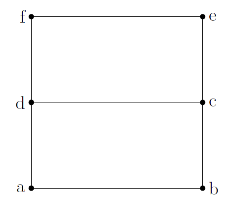
Figure 11:A circuit that has 3 loops and 2 junctions.
The locations at points and are considered “junctions”, because there are more than 2 segments of wire connected to that point. The points at locations , , and only have two segments of wire connected to them. The circuit in Figure 11 thus has 2 junctions.
A loop is a closed path that one can trace around the circuit without passing over the same segment of wire twice. The circuit in Figure 11 has 3 such loops, which we can identify using the letters at the various nodes of the circuit:
Note that it does not matter where one starts on the loop, only that one can identify how many different loops are present in the circuit.
19.3.1Junction rule
The junction rule states that: The current entering a junction must be equal to the current exiting a junction.
This is in fact a simple statement about conservation of charge. If charges are flowing into a junction (from one or more segments of wire in that junction), then the same amount of charges must flow back out of the junction (through one or more different segments of wire).
Consider the junction illustrated in Figure 13, comprised of 5 segments of wire, each carrying a different current. As shown, currents , , and flow into the junction, whereas currents and flow out of the junction.
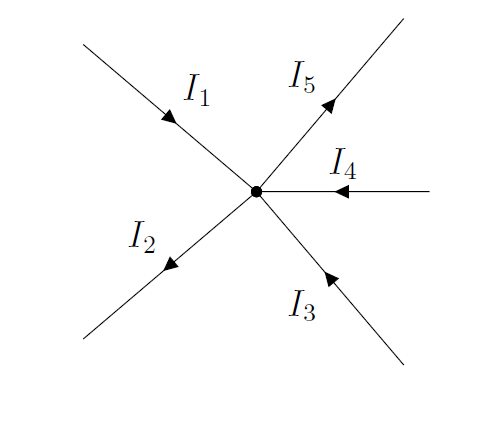
Figure 13:A junction with 5 segments and 5 currents.
The junction rule states that the current entering the junction must equal the current coming out of the junction. This allows us to relate the currents to each other in an equation:
19.3.2Loop rule
The loop rule states that: The net voltage drop across a loop must be zero.
This is a statement about conservation of energy, that we already noted in Example 19.1. Once you have identified a specific loop, if you trace a closed path around the loop, the electric potential must be the same at the end of the path as at the beginning of the path (since it is literally the same point in space). This means that if there is a voltage drop along the path (e.g. due to one or more resistors), then there must be equivalent voltage increases somewhere else on the path (e.g. due to one or more batteries). If this were not the case, it would be possible to have a path where charges could gain a net amount of energy by going around that path, which they could keep doing indefinitely and create an infinite amount of energy; instead, if charges gain potential energy in a battery, they must then lose exactly the same amount of energy inside one or more resistors along the path.
Figure 14 shows a loop (which could be part of a larger circuit) to which we can apply the loop rule. The loop contains two batteries, facing in opposite directions (which would not normally be a good use of batteries), as illustrated by the battery arrows.
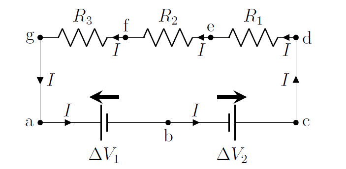
Figure 14:A loop with 2 batteries and 3 resistors.
The procedure for applying the loop rule is as follows:
Identify the loop, including starting position and direction.
Start at the beginning of the loop, and trace around the loop.
Each time a battery is encountered, add the battery voltage if you are tracing the loop in the same direction as the corresponding battery arrow, subtract the voltage otherwise.
Each time a resistor is encountered, subtract the voltage across that resistor (, from Ohm’s Law) if tracing the loop in the same direction as the current, add the the voltage otherwise.
Once you have traced back to the starting point, the resulting sum must be zero.
To illustrate the procedure, we trace out the loop in Figure 14. We thus start at point and trace the loop in the counter-clockwise direction.
Between points and we encounter a battery, and we are tracing in the opposite direction of that battery’s arrow, so we subtract the voltage from that battery: .
Between points and , we encounter a battery, and we are tracing in the same direction as that battery’s arrow, so we add the voltage from that battery: .
Nothing happens to the potential along the wire from to .
Between points and , we encounter a resistor, and we are tracing in the same direction as the current through that resistor, so subtract the voltage across that resistor: ).
Similarly, we subtract the voltages across resistors and , as we are tracing in the same direction as the current through those resistors: .
We are back at the beginning of the loop, so the terms must sum to zero.
We can now use the loop rule, which states that the sum of the above voltages must be zero:
This equation then gives us a relation between the various quantities (current, resistors, battery voltages) in the circuit which can be used to model the circuit.
19.4Applying Kirchhoff’s rules to model circuits
In this section, we show how to model a circuit using Kirchhoff’s rules. In general, one can consider a circuit to be fully modelled if one can determine the current in each segment of the circuit. We will show how one can apply the same procedure to model any circuit that contains batteries and resistors. The procedure is as follows:
Make a good diagram of the circuit.
Simplify any resistors that can easily be combined into effective resistors (in series or in parallel).
Make a new diagram with the effective resistors, showing battery arrows, and labelling all of the nodes so that loops can easily be described.
Make a guess for the directions of the current in each segment.
Write the junction rule equations.
Write the loop equations.
This will lead to independent equations that one can solve for the different currents in the circuit.
Once you have determined all of the currents, if some of them are negative numbers, switch the direction of those currents in the diagram (they will be negative if you guessed the direction incorrectly).
We will illustrate the procedure on the circuit shown in Figure 16, for which we would like to know the current through each resistor and each battery. The circuit contains 5 resistors (-), 2 real batteries (with ideal voltages and ), and 2 additional resistors to model the internal resistances of the real batteries (, )

Figure 16:A circuit that can be simplified and then solved with Kirchhoff’s rules.
Simplifying the resistors (step 2): In this circuit, resistors , and are in series, so that they can be combined into an effective resistor, :
With this simplification, we obtain the circuit illustrated in Figure 17
 have been combined into the effective resistor, $R_6$, to simplify the circuit.](/PhysicsArtOfModeling/build/bigcircuit_simp1-3c3b99d4c0dd89b374321bb250f98e3f.png)
Figure 17:The resistors , and in series from the circuit in Figure 16 have been combined into the effective resistor, , to simplify the circuit.
Next, we note that resistors and are in parallel and can be easily combined into a resistor, :
which leads to the circuit illustrated in Figure 18.
 have been combined into the effective resistor, $R_7$, to simplify the circuit.](/PhysicsArtOfModeling/build/bigcircuit_simp2-8ee8e95369dd9aaf4828ed561008a09d.png)
Figure 18:The resistors and in parallel from the circuit in Figure 17 have been combined into the effective resistor, , to simplify the circuit.
Finally, we note that and are in series and can be combined into an effective resistor, :
leading to the simplified circuit illustrated in Figure 19, which we have labelled with nodes and battery labels.
 have been combined into an effective resistor, $R_8$, to simplify the circuit.](/PhysicsArtOfModeling/build/bigcircuit_simp3-9d21ab2837bcef2bb16e322ff9dc6815.png)
Figure 19:The resistors and from the circuit in Figure 18 have been combined into an effective resistor, , to simplify the circuit.
Guessing the directions of the currents (step 4): Before we can write the equations from Kirchhoff’s rules, we need to label the currents in the circuit diagram. In general, it is not always obvious in which way the currents will go, so we make a guess that we can fix later if we guessed wrong.
In order to guess the current directions, choose one point on the circuit and move along a segment. Label the current in that segment and continue moving through the circuit, splitting up the current when a junction is encountered. Make sure to only have one current per segment. We guess the currents as follows, referring to Figure 20:
We start at point and move upwards to point . We will call the current in that segment, .
Since there is no junction, the current continues through the resistor to point .
There is a junction at point , so we split the current into currents (towards point ), and (downwards to point ).
We follow current first; flows from to , then down to , through the battery , and to point , where there is again junction.
We follow current , which just flows down to the junction at point , where it “meets up” with current .
Currents and both flow into the junction at point , and the current flowing out of the junction, through the battery , and towards point is, again, , since this current then flows up to point .
All segments of wire have a labelled current, so we are done guessing currents.
You can proceed in an analogous way for any circuit. The final circuit, with currents labelled, is shown in Figure 20:
.](/PhysicsArtOfModeling/build/bigcircuit_simp-f5331b714223884669deaf2da4c555e2.png)
Figure 20:Final and labelled circuit diagram that is simplified from the one in Figure 16.
We can now proceed using Kirchhoff’s rules to solve for the values of the currents in the circuit. It is useful to note that there are 3 unknown currents in this circuit; we thus hope that Kirchhoff’s rules will give us 3 independent equations.
Applying the junction rule (step 5): In the circuit from Figure 20, there are two junctions (at points and ), so we will get two equations from the junction rule. To apply the junction rule, the sum of the currents coming into the junction must be equal to the currents going out of the junction:
Note that the two equations are not independent (in fact, they are the same). It is generally the case that if there junctions, one will obtain less than independent equations (usually, equations will be independent). In this case, the two junctions only gave us one equation.
Applying the loop rule (step 6): This circuit contains 3 different loops: , , and , which will lead to 3 equations from the loop rule. We expect that these equations will not be independent, since this would lead to 4 equations and 3 unknowns when combined with the junction rule equation. Let us start with the loop :
From to , we trace through the battery in the opposite direction from the battery arrow: .
From to , we trace through the battery in the same direction as the battery arrow: .
From through and through to we go through the resistor in the opposite direction from the current, , in that resistor: .
From to , we go through the go through the resistor in the opposite direction from the current, , in that resistor: .
And we are back at the starting point, so the sum of the above terms is equal to zero.
which gives the equation:
Similarly, for the loop , we obtain:
and for loop :
Although it appears that we have obtained 3 additional equations, only two of these are independent. For example, if you sum the second and third equations (loops , and ), you simply obtain the first equation (loop ). In general, if there are different loops, one will obtain less than independent equations (usually independent equations, as we did here).
At this point, after choosing one of the junction equations, and two of the loop equations, we have 3 independent equations that we can solve for the 3 unknown currents\footnote{The 3 unknowns do not necessarily have to be the currents, and could be any combination of the currents, battery voltage and resistors. As long as there at most 3 unknown quantities, this circuit can be solved.}:
It is only a matter of some simple math to solve for the 3 unknowns from these 3 equations (which we carry out in the example below).
19.5Measuring current and voltage
In this section, we describe how one can build devices to measure current and voltage. A device that measures current is called an “ammeter” and a device that measured voltage is called a “voltmeter”. Nowadays, these are usually found within the same physical device (a “multimeter”), which can also measure resistance (by measuring voltage and current, resistance can easily determined). We will limit our description to the design of simple analogue ammeters and voltmeters.
As we will see in Chapter \ref{chapter:magneticforce}, it is straightforward to build a device that can measure very small amounts of current, by running the current through a coil in a magnetic field so that the coil can deflect a needle that indicates the amount of current. Such a device is called a “galvanometer” and is usually limited to measuring very small current (of order \si{mA}). In this section, we describe how one can use a galvanometer in order to build both ammeters to measure large currents and voltmeters.
19.5.1The ammeter
An ammeter is built by placing a galvanometer in parallel with a “shunt” resistor, . The shunt resistor is a small resistor that “shunts” (deflects) the current away from the galvanometer, so that most of the current goes through the shunt resistor. This is illustrated in Figure 27, which shows the galvanometer (circle with the inside), the internal resistance of the galvanometer, , and the shunt resistor, . The actual ammeter would be contained in a box and have two connectors (shown as and in the figure).
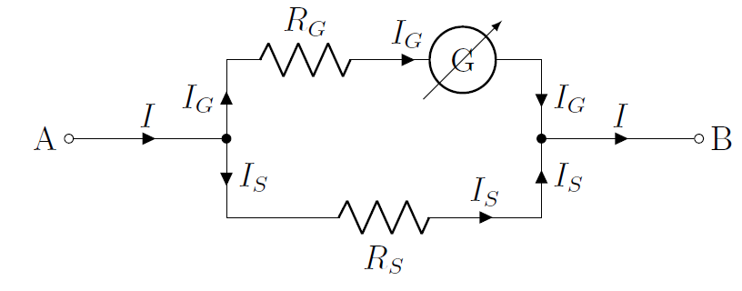
Figure 27:Constructing an ammeter from a galvanometer by placing a “shunt” resistor in parallel with the galvanometer.
By modelling the ammeter, we can determine the total current, , that we would like to measure using the known values of the resistors and the current, , measured by the galvanometer. Considering any of the two junctions, and a clockwise loop, we have:
which allows us to determine the current from the current , measured by the galvanometer. We also see that most of the current goes through the shunt (since is chosen to be smaller than ). The ammeter will have a total resistance, , given by:
In order to measure the current through a specific segment of a circuit, an ammeter must be placed in series with that segment (so that the current that we want to measure will pass through the ammeter). Figure 28 shows how to connect an ammeter (circle with the letter ) in order to measure the current through a resistor, .

Figure 28:An ammeter is placed in series with a resistor to measure the current through the resistor.
19.5.2The voltmeter
A voltmeter is constructed by placing a large resistor, , in series with a galvanomenter (that has internal resistance ), as illustrated in Figure 29. The voltmeter is designed to measure the potential difference between the terminals of the voltmeter (labelled and in the Figure).

Figure 29:Constructing an voltmeter from a galvanometer by placing a resistor in series with the galvanometer.
Given the values of the resistors, and the current measured by the galvanometer, one can easily determine the potential difference between points and , since the current measured by the galvanometer goes directly through each resistor:
In order to measure a potential difference across a component, the voltmeter must be placed in parallel with the component. Figure 30 shows how to connect a voltmeter (circle with the letter ) in order to measure the voltage across a resistor, .
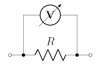
Figure 30:A voltmeter is placed in parallel with a resistor to measure the voltage across the resistor.
When using an ammeter or a voltmeter, you will notice that these usually have buttons or dials to choose the range of currents or voltages to be measured. All the dial does is change the value of the shunt or series resistor in order to maintain a given maximum current through the galvanometer. An ohmmeter, to measure resistance, is simply an ammeter with a built-in fixed potential difference (so that by measuring current across a known potential difference, the resistance of the component can be determined).
19.6Modelling circuits with capacitors
So far, we have modelled circuits where the current does not change with time. When a capacitor is included in a circuit, the current will change with time, as the capacitor charges or discharges. The circuit shown in Figure 32 shows an ideal battery\footnote{The model still holds for a real battery, since the internal resistance of the battery can just be included into the resistance of the resistor, .} (), in series with a resistor (), a capacitor (, two vertical bars) and a switch () that is open.

Figure 32:A simple circuit with a resistor, battery, and capacitor.
When the switch is open, current cannot flow through the circuit. If we assume that the capacitor has no charge on it, once we close the switch, current will start to flow and charges will accumulate on the capacitor. Electrons will leave the negative terminal of the battery, flow through the resistor and accumulate on the left side of the capacitor, which acquires a negative charge. This pushes electrons off of the right hand side of the capacitor, which then becomes positively charged. The electrons from the positive side of the capacitor then flow into the positive side of the battery, completing the circuit.
Eventually, the charges on the capacitor will build up to a point were they prevent any further flow of current. Once the left side of the capacitor is at the same potential as the left side of the battery, current will cease to flow. That is, eventually, the potential difference across the capacitor will be equal to that across the battery, and we can think of this as a circuit used to charge a capacitor. The current is high when the switch is first opened, but eventually goes down to zero as the capacitor charges. The current is thus time-dependent.
We can model this simple circuit (with the switch closed) using Kirchhoff’s loop rule. The sum of the voltages across each component must sum to zero:
where we used the fact that the charge, , on a capacitor is related to the potential difference, , across the capacitor by . The current, , is the rate at which charges flow through the circuit, and is thus equal to rate at which charges accumulate on the capacitor:
Substituting this into the loop equation, we obtain a separable differential equation for the charge on the capacitor as a function of time, :
This is similar to differential equations that we have solved previously (in fact, it is the same equation as in Example 6.4 where we looked at the effect of velocity-dependent drag). The solution to the equation, assuming that the switch is closed at , is given by an exponential:
Thus, the charge on the capacitor starts at zero when the switch is closed, and grows asymptotically until it reaches a value of , which corresponds to the capacitor having the same potential difference across it as the battery. The value is called the “time constant” of the RC circuit, and corresponds to the time at which the capacitor will reach about of its maximal charge. The current as a function of time is given by:
and we can see that at time the current is the same as if there were no capacitor present, and the current then decreases exponentially until it reaches zero.
19.7Summary
Batteries are usually formed from a collection of electrochemical cells. Batteries provide a constant electric potential difference across their terminals, usually sustained by a chemical reaction, as long as the current through the battery is not too large (or the chemical reactions cannot be sustained).
An ideal battery has no resistance and can be modelled as a simple potential difference in a circuit. A real battery includes an internal resistance and be modelled in a circuit as an ideal battery in series with a resistor. The voltage across the terminals of a real battery is equal to the voltage across the terminals of the ideal battery only when no current flows through the internal resistance.
Circuits are modelled using circuit diagram that include components (such as batteries and resistors) and wires. Wires are always modelled as having no resistance, since their resistance can be included by placing the appropriate resistor along the wire. The electric potential is always constant along a wire with no resistance. When modelling a circuit, one always models the direction of conventional current; that is, current is always indicated as the direction in which positive charges flow (even if in reality, it is negative electrons that flow in the opposite direction).
Circuits should be thought of in terms of conservation of energy. Components produce a potential difference between sections of wire. Batteries correspond to an increase in potential (if going from the negative to the positive terminal), whereas resistors corresponds to a decrease in potential (if going in the same direction as current through the resistor).
Kirchhoff’s rules allow us to model complex circuits. The junction rule states that: The current entering a junction must be equal to the current exiting a junction. This is a statement about conservation of charge. If charges are flowing into a junction, then the same amount of charges must flow back out of the junction per unit time.
The loop rule states that: The net voltage drop across a loop must be zero. This is a statement about conservation of energy indicating that as the potential energy of a positive charge increases as it goes through a battery, it will decrease by the same amount if it goes through a resistor that is connected to the terminals of that battery.
In order to apply the loop rule, we strongly suggest using the following procedure, after having made a clear, labelled diagram showing battery arrows and currents in the circuit:
Identify the loop, including starting position and direction.
Start at the beginning of the loop, and trace around the loop.
Each time a battery is encountered, add the battery voltage if you are tracing the loop in the same direction as the corresponding battery arrow, subtract the voltage otherwise.
Each time a resistor is encountered, subtract the voltage across that resistor (, from Ohm’s Law) if tracing the loop in the same direction as the current, add the the voltage otherwise.
Once you have traced back to the starting point, the resulting sum must be zero.
In general, we suggest the following procedure in order to use Kirchhoff’s rules to model any circuit:
Make a good diagram of the circuit.
Simplify any resistors that can easily be combined into effective resistors (in series or in parallel).
Make a new diagram with the effective resistors, showing battery arrows, and labelling all of the nodes so that loops can easily be described.
Make a guess for the directions of the current in each segment.
Write the junction rule equations. Usually, you will get independent equations for loops.
Write the loop equations. Usually, you will get independent equations for loops.
This will lead to independent equations that one can solve for the different currents in the circuit.
Once you have determined all of the currents, if some of them are negative numbers, switch the direction of those currents in the diagram (they will be negative if you guessed the direction incorrectly).
Current and voltage measuring devices (ammeters and voltmeters, respectively) can be constructed from a galvanometer, which measures small currents. An ammeter is constructed by placing a small shunt resistor in parallel with the galvanometer so that most of the current passes through the shunt resistor. The resulting ammeter must be placed in series with a component in order to measure the current through that component.
A voltmeter is constructed by placing a resistor in series with the galvanometer in order to reduce the current through the galvanometer. The resulting voltmeter must be placed in parallel with a component in a circuit in order to measure the voltage across that component. Note that because voltmeters and ammeters have a non-zero resistance, they will affect the circuit once they are connected.
When a capacitor is placed in a circuit, the current in the circuit will no longer be constant in time. If an uncharged capacitor with capacitance, , is placed in a series circuit with a battery and a resistor of resistance, , the capacitor will charge until the voltage across the capacitor is equal to that across the battery. Once the capacitor is charged, current ceases to flow in the circuit. The charges on a capacitor accumulate with a rate that decays exponentially; it will take an infinite amount of time for the capacitor to become fully charged. It will be charged to about 63% of maximum charge after a period of time, , called the time constant of the capacitor.
19.8Thinking about the material
19.9Sample problems and solutions
19.9.1Problems
19.9.2Solutions
Solution 19.1
a. In this case, the capacitor is discharging as a function of time. At time , the voltage across the capacitor is . We can model this discharging circuit in a similar way as we modelled the charging circuit.
We start with Kirchhoff’s loop rule, which leads to a differential equation for the charge stored on the capacitor as function of time, :
This differential equation is straightforward to solve, since it says that the derivative of is equal to a constant multiplied by . Thus, must be an exponential function:
where is the (unknown) charge on the capacitor at . You can easily verify that taking the derivative of this equation will result in the differential equation being satisfied.
Now that we have an equation for the charge as a function of time, it is straightforward to find the current, since it is just the time derivative of the charge. The current as a function of time, , is given by:
where is the current at .\
We also know that the current through the resistor at is given by Ohm’s Law, since, at that time, the voltage, :
We then know that the current, at time , is equal to , allowing us to determine the capacitance:
b. To find the charge stored in the capacitor at , we can use the function that we determined before:
where we can determine , now that we know the capacitance. is the charge on the capacitor at time , when the voltage across the capacitor is :
At , the charge on the capacitor is thus:
Solution 19.2
In order to know the voltage across one of the resistors, we need to determine the voltage that is across the battery. Once we have determined the voltage across the battery, the voltage across one of the resistors will just be half of that across the battery, since the two resistors have the same resistance.
We can model the circuit with the voltmeter in place, since we know the voltage across the parallel combination of the voltmeter and resistor (that voltage which is readout by the voltmeter). We can combine the voltmeter and one of the resistors into a an equivalent resistor, :
Now that we have the effective resistance as well as the voltage drop across that effective resistor, we can solve for current through the circuit:
Now that we have the current, we can combine the known resistances and determine the voltage drop across the battery.
Thus, with no voltmeter present, the voltage across each resistor is .