Overview
Introduction
These experiments will be carried out with breadboards, multimeters, and DC power supplie. However, a useful virtual component to accompany the work on the lab bench is to use the PhET simulator below. Click on the “Lab” tab.
Figure 1:A PhET simulation to explore simple circuits.
Background
Ohm’s Law says
or voltage equals the current times the resistance. is in Volts (Volts are Joules/Coulomb). is in amperes (or Coulomb per second), and is in Ohms (units you could work out from the others). These are SI units. Voltage, also called electric potential, is the source of energy pushing electrons through a typical circuit. Flowing charges, or current, is a result of the voltage pushing charges against electrical resistance. As voltage increases, the current should increase linearly for a particular resistance.
Circuit Loop Rules
The word circuit comes from the idea that electronic circuits make loops. A circuit or electronic loop must conserve energy. This leads to two circuit rules.
The sum of voltages around a loop are zero, e.g., energy per charge input from a battery equals energy per charge dissipated by a resistor.
The current through a circuit or electronic loop is constant throughout the loop.
In Figure 2, on the left is a circuit shown as we might see in the lab with a battery and a resistor. On the right is the equivalent circuit diagram. We assume wires are ideal, with zero resistance. The circles with dashed lines are points where the circuit can be broken to add more elements such as a current meter.
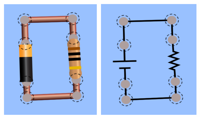
Figure 2:Circuit showing a single resistor connected to a battery or power source. On the left is the PhET cartoon with a battery and 10 Ohm resistor. On the right is the circuit diagram.
Identifying Resistors
The resistors we will use have four or five colored bands on them. These bands quantify the resistance as shown in Figure 3.
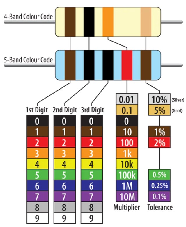
Figure 3:Circuit showing a single resistor connected to a battery or power source. On the right is the PhET cartoon with a battery and 10 Ohm resistor. On the left is the circuit diagram.
For example, a resistor with yellow, violet, red, and silver bands gives the numbers . This indicates the resistance is .
Measuring Voltage and Current
🔌 Voltage is Measured in Parallel
Why in parallel?
Voltage is the potential difference between two points. To measure that, you need to compare the electric potential at one point relative to another.
How?
Place the multimeter probes across (in parallel with) the component.
This allows the meter to measure the drop in electric potential through that component.
Example:
To measure the voltage across a resistor, you touch:
One probe to the resistor’s current input side.
The other to the current output side.
See Figure 4
💡 Think of it like checking the pressure difference across a valve in a water pipe.
⚡ Current is Measured in Series
Why in series?
Current is the flow of electric charge through a circuit. To measure it, the current must pass through the multimeter so it can count how much is flowing.
How?
Break the circuit and insert the multimeter in line with the component (in series).
This forces all the current flowing through that component to also go through the meter.
Example:
To measure the current through an LED, you’d:
Disconnect one side of the LED.
Connect the multimeter between the disconnected lead and where it was attached.
💡 This is like measuring water flow by putting a meter in the pipe—the water (or electrons) must pass through it.
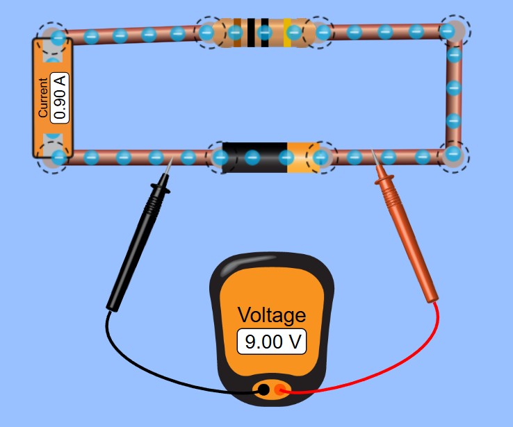
Figure 4:A visual for how to measure voltage and current.
Quick Summary:
| Measurement | Connection Type | Why? |
|---|---|---|
| Voltage | Parallel | Measures potential difference between two points |
| Current | Series | Measures flow of charge through a path |
Experiment
Part 1 – Single Resistor
Set up the circuit shown above with a single resistor in the simulator and on the lab bench. From the colored bands, determine the resistance and set the same resistance in the simulator. On the lab bench, you will use a power supply instead of a battery so that you can adjust the voltage. Apply the voltages as shown in Table 1 and measure the current flows for each applied voltage.
Table 1:Applied voltages and measured currents.
| Voltage (V) | Current (A) |
|---|---|
| 0.5 | |
| 1.0 | |
| 1.5 | |
| 2.0 | |
| 2.5 | |
| 3.0 |
import numpy as np
import matplotlib.pyplot as plt
from scipy.optimize import curve_fit

#define a linear function
def line_fit (x, m, b):
	return m*x + b

#Define your data
V = np.array([0.5, 1.0, 1.5, 2.0, 2.5, 3.0])
V_unc = np.ones(6)*0.05 #adjust this to the appropriate uncertainty
I = np.array([1,2,3,4,5,6]) #enter your current values
I_unc = np.ones(6)*0.1 #adjust this to the appropriate uncertainty

#Do the linear fit
parms, cov = curve_fit(line_fit, I, V, sigma=V_unc, absolute_sigma=True)
print("slope =", parms[0], "+/-", np.sqrt(cov[0][0]))
print("intercept =", parms[1], "+/-", np.sqrt(cov[1][1]))

plt.errorbar(I, V, yerr=V_unc, fmt='ob') #plot the data
plt.plot(I, parms[0]*I+parms[1])
plt.xlabel('Current (A)')
plt.ylabel('Voltage (V)')
plt.show()
Part 2 – Series Resistors
Set up a “series” circuit with two resistors in series as shown in Figure 5. From the colored bands, determine the resistances and set those same resistances and voltages in the PhET simulator. Apply the input voltages as shown in Table 1 and measure the currents at the locations indicated in Figure 6. Measure the voltage across each resistor (two voltage measurements).

Figure 5:Circuit showing a two resistors in series connected to a battery or power source.

Figure 6:Three locations identified for measuring current in the series circuit.
Part 3 - Parallel Resistors
Set up a “parallel” circuit with two resistors in parallel as shown in Figure 7. From the colored bands, determine the resistances and set those same resistances and voltages in the PhET simulator. Apply the input voltages as shown in Table 1 and measure the currents at the locations indicated in Figure 8. These three currents should be different from one another. If you have any trouble, use the PhET simulation to help troubleshoot. Measure the voltage across each resistor (two voltage measurements).

Figure 7:Circuit showing a two resistors in parallel connected to a battery or power source.

Figure 8:Three locations identified for measuring current in the parallel circuit.
Part 4 - Application: Voltage Divider to Measure Temperature
A voltage divider is a series resistor circuit. As you saw in Part 2 – Series Resistors, the voltage across resistors in series varies according to the values of resistance, i.e., a large resistor will have a proportionally larger voltage drop than a smaller resistor in a series connection. A voltage divider is shown in Figure 9 and is the same circuit as Figure 5.
Voltage Divider Overview
A voltage divider has two essential parts: the circuit and the equation.
The Circuit
A voltage divider is created by connecting two resistors in series across a voltage source. You might see this circuit drawn in slightly different ways, but the basic setup is always the same.

Figure 9:A voltage divider circuit with an unknown resistor .
We will label the resistor connected closest to the input voltage () as , and the resistor connected closer to ground as , where we know the input voltage and the resistance of . is a variable resistance that changes with temperature. The voltage measured across is called .
That’s really all there is! is the “divided” voltage — a specific fraction of the input voltage.
The Equation
To use a voltage divider, you need to know three values. In this case, we know the input voltage (), the resistor values , and we measure the voltage across the known resistor . With these, you can calculate the unknown resistance () using resistor circuit formulas.
Voltages sum:
Ohm’s Law of equation (1) for a series circuit is a constant current flowing through both resistors. We are free to substitute any with , where and . Together, we can write
Equation (3) shows that the unknown resistance can be calculated by measuring the voltage of the known resistor.
The experiment
Measure the room temperature resistance of the thermal resistor with your multimeter. Choose a resistor for that is similar in resistance. Set up a voltage divider circuit with two resistors in series as shown in Figure 9. Set , and measure the voltage drop across . Calculate the resistance of the thermal resistor . Place the thermal resistor in three different environments, one hotter, one colder, and one equal to room temperature. Calculate the resistances of the thermal resistor. Repeat these measurements two more times.