Chapter 14 - Fluid mechanics
14.1Overview
In this chapter, we introduce the tools required to model the dynamics of fluids. This will allow us to model how objects can float, how water flows through a pipe, and how airplane wings create lift. We will start by introducing the concept of pressure and modelling static fluids (hydrostatics) before developing models for fluids that flow (hydrodynamics). Fluids are generally defined as the phase of matter in which atoms (or molecules) are only loosely bound to each other, such as in gases or liquids. Most of the formalism that we develop will apply to any fluid (gas, liquid, plasma), although we will often restrict ourselves to modelling the most simple situations (e.g. laminar flow of an incompressible liquid).
14.2Pressure
The pressure exerted by a force, , over a surface with area, , is a scalar quantity, , defined as:
where is the component of the force perpendicular to the surface. The SI unit for pressure is the Pascal (). Pressure is related to the area, , over which a force is exerted, and can be thought of as a measure of how concentrated that force is. For example, a force of exerted through a needle (a small area) will result in a much larger pressure than if that force was exerted by a flat hand (a larger area).
When a force is exerted on a fluid, it creates pressure that we model as being everywhere in the fluid. For each element in the fluid, the pressure from the surrounding fluid exerts an inwards force on the element from all directions (see Figure 2). In reaction, the element exerts an outwards force in all directions, and these forces act on neighbouring elements.
This is somewhat analogous to the tension that exists everywhere in a rope, where each element of the rope experiences forces from the neighbouring elements in rope that try to “pull it apart”. Pressure can be thought of as a “negative” tension, in that the material under pressure is experiencing forces trying to collapse the element onto itself, rather than trying to pull it apart. To create a tension in a rope, one would exert an outwards force on the rope (in order to stretch it), so that the rope exerts an inwards force in reaction. In order to create pressure in a fluid, one must exert an inwards force on the fluid, which then exerts an outwards force in reaction.
If we consider a small cubic volume of fluid, as depicted in the centre of Figure 2, that element of fluid will experience inwards forces in all directions from the pressure in the surrounding fluid, as illustrated by the arrows. If the forces from the pressure result in no net force on the fluid element, then we say that the fluid is in hydrostatic equilibrium, and the element of fluid will be at rest in an inertial frame of reference.

Figure 2:A small element inside of a fluid with pressure will experience no net force from the pressure in the fluid, since the force associated with the pressure in the fluid is exerted in all directions.
Consider, instead, an element of fluid that at the edge of a container for the fluid (e.g. a cup of water), as depicted in Figure 3.
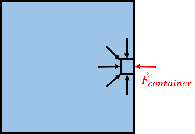
Figure 3:At the edge of a container, a small element of fluid will exert an outwards force on the container, and the container will exert an inwards force on the element of fluid.
In this case, there is no fluid on the right-hand side of the fluid element to exert a force towards the left. If the fluid element is in equilibrium, it must then be the container that exerts that force, , on the fluid. By Newton’s Third Law, the element of fluid exerts an outwards force on the container. This is true at all points on the surface of container, which will all experience an outwards force from the pressure of the fluid. If the pressure is constant over a surface, the magnitude of the outwards force on the surface will be equal to the pressure of the fluid multiplied by the area of that surface.
If you place an empty sealed tin can under water, the water will exert a pressure on all of the surfaces of the tin can that leads to a net inwards force on all surfaces of the tin can. If the water pressure is high enough, the tin can will get crushed. If, on the other hand, the tin can is allowed to fill with water, it will not get crushed, as the water inside the tin can will have the same pressure as the water outside the tin can and will exert an equal net outwards force on all surfaces of the tin can. The net force on each surface of the can will be zero, and the tin can will not get crushed, no matter how high the water pressure is.
In general, if there is an interface with fluid on either side of it a different pressures, it is the difference in pressure on either side of the interface that determines the net force exerted on the interface, rather than the absolute pressure.
14.2.1The effect of gravity
When discussing Figure 2, we argued that the fluid exerts an equal force, from all directions, on the fluid element, so that the net force on the fluid element is zero. This is not quite correct in the presence of gravity, where the fluid element will have a weight. Thus, if the fluid element is to be in equilibrium, the upwards force (and pressure) from the fluid below must be higher than that from the fluid above the fluid element.
Figure 4 shows an element of fluid that has a height and a surface area in the horizontal plane. The pressure, , in the fluid below the fluid element must be higher than the pressure, , above the fluid element, if the fluid element is in equilibrium.
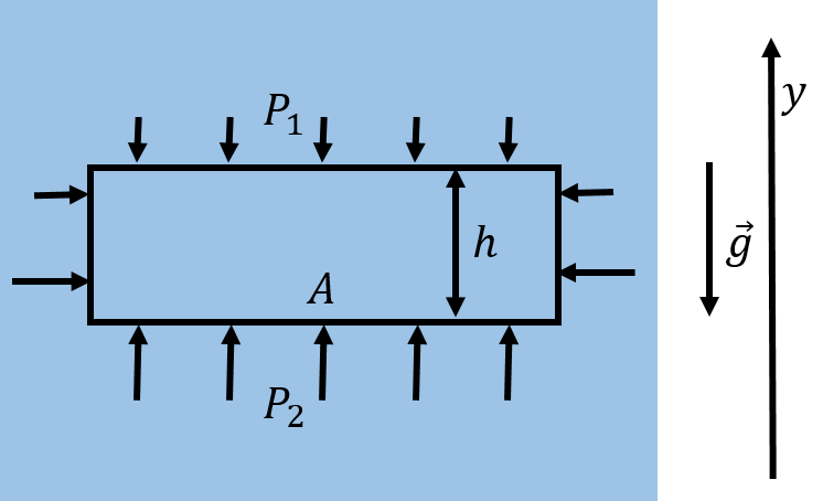
Figure 4:In the presence of gravity, the pressure below an element of fluid must be larger if the fluid element is to remain in equilibrium.
The element of fluid has a total mass, , given by:
where, , is the volume of the fluid, and, , its density.
The net (horizontal) force exerted by the external fluid on the fluid element is zero along the vertical surfaces. Let be the pressure in the fluid above the fluid element, and be the pressure below the fluid element. If we choose a axis that is positive upwards and the fluid element does not accelerate in the vertical direction, then the component of Newton’s Second Law, written for the fluid element, is:
where we used the fact that the force resulting from a pressure is given by the pressure multiplied by the area over which it is exerted. We thus find that the difference in pressure due to gravity in a fluid between two positions, and , is given by:
where the axis is defined to increase in the upwards direction. Since the pressure in the fluid depends on the location in the fluid, we say that there is a “pressure gradient” in the fluid.
We have assumed that the density of the fluid, , is constant, and that the fluid cannot be compressed. This is a very good approximation for a liquid such as water, but not for a gas, whose density will depend on its pressure. If the fluid were a gas (e.g. a column of air in our atmosphere), both the density and the pressure will change as a function of height. We can easily take this into account in our model, if we consider the fluid element to have a very small height, , instead of the finite height, , as in the derivation above. A fluid element with an infinitesimal height, , is illustrated in Figure 6.
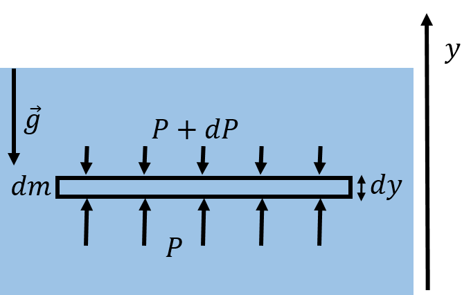
Figure 6:Pressure gradient from gravity on an infinitesimal fluid element.
In the very small height, , the density of the fluid, , can be taken to be constant, and the infinitesimal element of fluid will have a mass :
We can model the pressure exerted by the fluid above the fluid element as , and the pressure exerted by the fluid below as , where is a small (negative) change in pressure[38]. The component of Newton’s Second Law written for the infinitesimal fluid element is thus:
We can thus determine how pressure changes with height, :
This tells us that the rate of change of pressure with increasing is negative; in other words, the pressure decreases as the elevation increases, as we had already concluded. We can integrate the equation to obtain the change in pressure in going from to :
If the density, , is constant, then this leads to (4). Note that, thus far, we have only modelled how pressure in a fluid changes with height, but we have not determined the absolute pressure in a fluid.
14.2.2Pascal’s Principle
Pascal’s Principle states that if an external pressure is exerted on a fluid, the pressure everywhere in the fluid increases by that amount. For example, if a fluid is contained in a piston with a cross-section area, , and a force, , is exerted on the piston (Figure 7), then the pressure everywhere in the fluid increase by .

Figure 7:A force exerted on the piston will increase the pressure everywhere in the fluid.
If we wish to determine the absolute pressure in the water at some depth, , in the ocean, we need to include the fact that the Earth’s atmosphere exerts a net downwards force on the surface of the ocean in addition to the fact that the pressure changes with depth due to gravity. The pressure from the air in the Earth’s atmosphere is called “atmospheric pressure”, and depends on a variety of conditions, such as the weather. The average pressure from the atmosphere is . If the atmospheric pressure is at the surface of the ocean, then the pressure at some depth, , is given by:
where is the density of water. As a consequence, the pressure at any depth, , in a fluid is the same everywhere at that depth in the fluid.
14.2.3Measuring pressure
In this section, we describe how one can design instruments to measure pressure. The most straightforward device is a manometer, which is constructed using a U-shaped tube filled with a fluid of known density, , as shown in Figure 10.

Figure 10:A manometer can measure the difference between a pressure and atmospheric pressure, . That difference is called “gauge pressure”.
A manometer can be used to measure a pressure relative to atmospheric pressure, . One end of the tube is open to atmospheric pressure, and the other is connected to the fluid (e.g. a gas) for which we want to measure the pressure. If the pressure being measured is larger than atmospheric pressure, the fluid in the manometer will experience a greater downwards force on the side of the pressure to be measured than on the side open to atmospheric pressure, as shown in Figure 10. There will be a difference, , in the level of the fluid on each side of the tube, which is directly proportional to the difference in pressure between the two sides of the tube.
Consider the point in the fluid at location in Figure 10, where the pressure is , the pressure to be measured. The point in the fluid at location , which is at the same height in the fluid, must have the same pressure as point . We can write the pressure at point , , as the sum of the atmospheric pressure and the pressure from the column of water of height, :
Since this must also be equal to the pressure at point , we can find the difference between the pressure we want to measure and atmospheric pressure:
The difference between a pressure and the atmospheric pressure is called “gauge pressure”, and is all that we can measure if we do not know the absolute value of the atmospheric pressure. Using a manometer, the gauge pressure is given by , whereas the “absolute pressure”, , is given by adding the atmospheric pressure to the gauge pressure, . Most pressure measuring devices (“pressure gauges”), measure pressure relative to atmospheric pressure, using a similar mechanism.
The atmospheric pressure at a location on Earth varies based on the weather. A barometer is an instrument designed to measure the atmospheric pressure. A simple barometer can be built from a manometer, with one end closed, as illustrated in Figure 11.

Figure 11:A barometer constructed from a manometer to measure relative changes in atmospheric pressure.
One end of the manometer is sealed on a day where the atmospheric pressure is, say, , while the other end of the tube is left open. The height difference, , between the fluid in either side of the tube is a measure of how different the current atmospheric pressure, , is relative to the pressure, , when the manometer was sealed. In Figure 11, the barometer is shown on a day where the atmospheric pressure is lower than on the day the manometer was sealed. The difference in pressure is given by:
if we define to be positive when the side with the pressure is higher (so is negative in Figure 11 and is less than ).
We can also measure the absolute atmospheric pressure if we evacuate the air out of the sealed end of the tube, so that . When doing so, the difference in height between the fluid on either side of the manometer is a measure of the absolute atmospheric pressure.
14.3Buoyancy
In this section, we examine how the pressure gradient in a fluid leads to a force of buoyancy on an object that is immersed in the fluid.
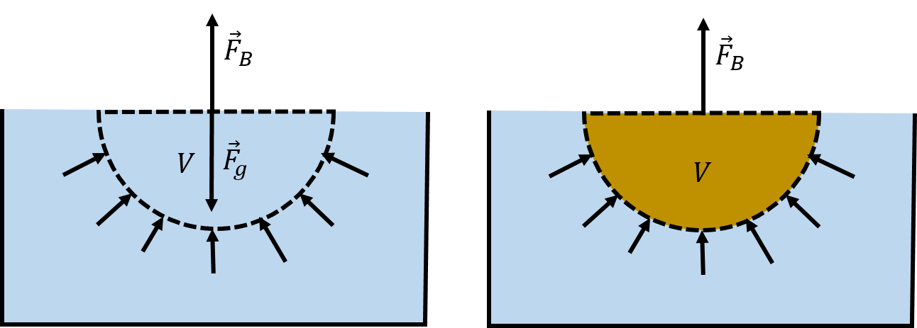
Figure 14:(Left:) The weight of a fluid element, , is supported by the net upwards force from the pressure, , of the fluid below it. (Right:) If the fluid element is removed and replaced with an object, there will still be the same net upwards force, , from the pressure of the fluid, which is now exerted on the object.
In the left panel of Figure 14, we show a hemi-spherical element of fluid with a volume . The weight of the element of fluid, , is supported by the net upwards force, , exerted by the pressure of the fluid surrounding the fluid element. The mass, , of the element of fluid is given by:
where is the density of the fluid. The net force from the pressure, , must thus have the same magnitude as the weight:
Now, suppose that the fluid element is “displaced” and replaced by the hull of a boat, as shown in the right panel of Figure 14. The net upwards force from the pressure of the fluid must remain the same, , but that force is now exerted on the hull of the boat. We call that force the force of “buoyancy”, which is the reason that a boat can float and the reason that you feel lighter when walking in a swimming pool than on land.
Thus, if an object displaces a volume, , of a fluid with density , when immersed in the fluid, that object will experience an upwards force of buoyancy, , with magnitude:
This “principle” was originally discovered by Archimedes, who stated that the force of buoyancy is equal to the weight of the displaced fluid. Note that we drew the fluid element at the surface of the fluid, but this is not required, and a force of buoyancy will be present if the object is completely immersed in the liquid. If you refer back to Figure 4, you will recall that the net upwards force on an element of fluid must be equal to its weight, even if the fluid element is completely immersed.
14.4Hydrodynamics
In the previous sections we developed “hydrostatic” models for fluids when those fluids are at rest (in some inertial reference frame). In this section, we develop “hydrodynamic” models to discuss what happens when fluids flow. We will restrict our models to fluids that flow in a “laminar” fashion, rather than a “turbulent” fashion.
Laminar flow is the flow of a fluid when each particle in the fluid follows a path that can be represented by a line (a “streamline”). Turbulent flow is the flow of a fluid where particles can follow rather complex paths, usually involving “Eddy currents” (little whirlpools). The two types of flow are illustrated in Figure 15.

Figure 15:Laminar (left) and turbulent (right) flow of a fluid around an object.
14.4.1Continuity of flow
Consider the laminar flow of a fluid through a pipe whose cross-sectional area narrows from to in the direction of flow, as illustrated in Figure 16.

Figure 16:Laminar flow of a fluid in a narrowing pipe.
The particles that make up the fluid have a speed at the wide end of the pipe and speed at the narrow end. The equation of continuity is based on the premise that the fluid that enters the pipe must exit the pipe, as there is nowhere else for the fluid to go. That is, if during a period of time, , a mass, , of fluid enters the wide end of the pipe, then during that same period of time, the same mass of fluid must exit the narrow end of the pipe.
During a period of time, , the fluid at the wide end of the pipe will travel a distance . Thus, a volume of fluid, , will enter the wide end of the pipe:
Similarly, during that period of time, a volume will exit the narrow end of the pipe:
If the fluid is compressible, its density can change. Let be the density of the fluid at the wide end of the pipe and be the density of the fluid at the narrow end. The mass of fluid, , entering the wide end of the pipe is given by:
The mass of fluid exiting the narrow end of the pipe is given by:
The mass of fluid entering the wide end of the pipe must equal the mass exiting the narrow end of the pipe:
Leading to the equation of continuity:
The quantity has dimensions of mass per time, and corresponds to the mass of fluid passing through a cross section per unit time.
If the fluid is incompressible, as are most liquids, then the density is the same on both sides of the pipe, and the equation simplifies to:
For a liquid, we can define the “volumetric flow”, , as:
where is the cross-sectional area of the surface through which a fluid with speed, , flows[39]. has the dimension of volume per time, and corresponds to the volume of fluid passing through the cross section per unit time. For an incompressible fluid, the equation of continuity is thus equivalent to stating that the volumetric flow, , of the fluid is a constant.
14.4.2Bernoulli’s Principle
In this section, we examine how the pressure and speed of a fluid change as the fluid flows. We will restrict ourselves to discussing the laminar flow of an incompressible fluid with no friction. Bernoulli was the first to quantitatively describe the flow of incompressible fluids, and we will show in this section how to derive “Bernoulli’s Principle”.
Consider the laminar flow of an incompressible fluid through a pipe that changes height, from to , as well as cross-sectional area, from to , as shown in Figure 18. The figure shows an element of fluid, in blue, as it moves through the pipe. The top panel corresponds to the location of the fluid element at time , whereas the bottom panel shows the location of the element of fluid at time .
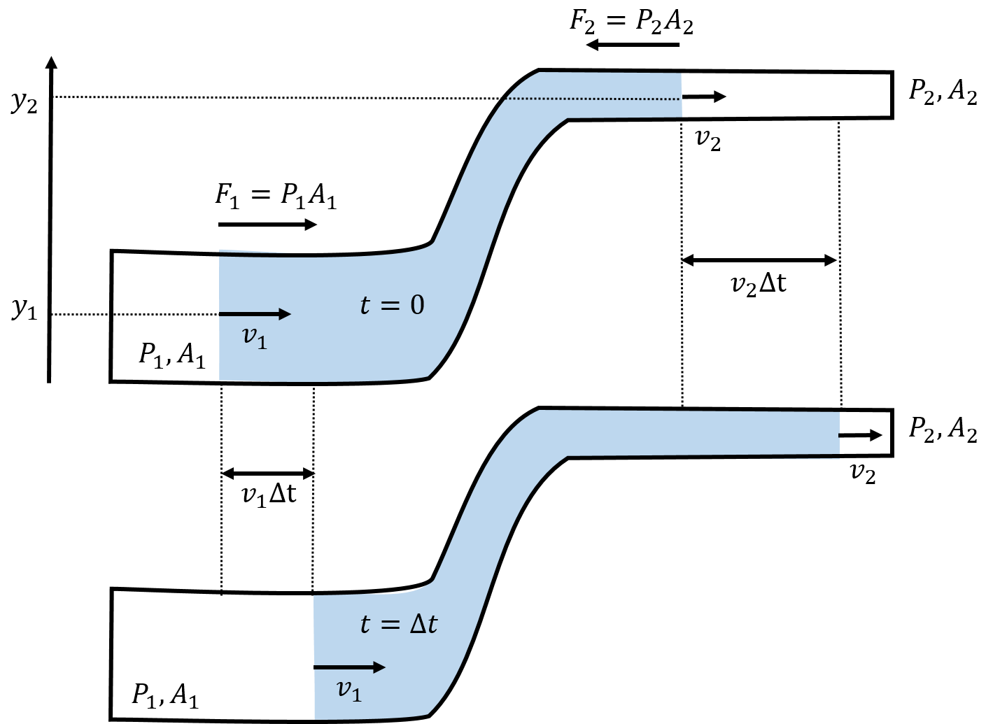
Figure 18:Laminar flow of an incompressible fluid through a pipe that changes cross-sectional area and height in the direction of flow. An element of fluid, in blue, is shown at time (top panel), and then, at a later time, (bottom panel).
To model how the fluid moves through this pipe, we can use energy and the Work-Energy Theorem. We start by considering the amount of work done on the element of fluid as it moves from the position in the top panel to the position in the bottom panel.
The fluid that is to the left of the element of fluid exerts a pressure, , on the fluid element that leads to a net force, , towards the right. Similarly, the fluid to the right of the element of fluid exerts a net force in the opposite direction, due to the pressure on that side of the fluid element.
In a period of time, , the left part of the fluid element will move a distance , while the right part of the fluid element will move a distance . We can calculate the work done by each force, defining positive work to be in the direction of motion:
Gravity will also do (negative) work on the fluid as it changes height. In a period of time, , a mass of fluid, , will move from position to position . The mass of fluid that changes height is given by the part of the fluid that moves a distance, , on the right side of the pipe:
Because of the equation of continuity, this is also equal to the mass of fluid that moves a distance, , on the left side of the pipe:
since .
The force of gravity will thus do negative work on that mass element:
The net work done on the element of fluid over the time is thus:
Note that, because of the equation of continuity, , we can factor out a from each term:
The net work done on the fluid must equal the change in kinetic energy, , of the mass element, , from one end of the pipe to the other:
Using the Work-Energy Theorem, we have:
We can re-arrange this so that all the quantities for each side of the pipe are on the same side of the equation:
Since the locations 1 and 2 that we chose are arbitrary, we can state that, for laminar incompressible flow, the following quantity evaluated at any position is a constant:
This statement is what we call Bernoulli’s Equation, and is equivalent to conservation of energy for the fluid. If the fluid is not flowing (), then this is equivalent to the statement of hydrostatic equilibrium that we derived in (4):
If the flow of the fluid is at constant height (), then Bernoulli’s equation can be written as:
If a fluid is flowing at constant height such that (as in Figure 16), then ; that is, the pressure in the fluid is lower if the fluid is flowing faster. Note that is the pressure inside the fluid and is not related to the force that would be exerted by the fluid if it were to collide with an object. It makes sense that the fluid has a lower pressure where it is moving faster, because the net force exerted on the fluid is related to the difference in pressure on either side of the fluid. The fluid will accelerate in the direction where pressure decreases, thus it will be moving faster when it is in a region of low pressure.
Bernoulli’s principle can be used to describe many phenomena. For example, an airplane wing (technically, an “airfoil”) creates lift because the pressure of the air above the wing is lower than the pressure of the air below the wing. This is illustrated in Figure 19, which shows that the laminar flow of the air creates a low pressure area above the wing. As the stream lines of air encounter the wing, those that are above the wing get compressed together, which leads to a faster speed of the air above the wing (equation of continuity). The resulting difference in air pressure above and below the wing results in a net upwards force on the wing.

Figure 19:Laminar flow of air around a airfoil. The curvature of the asymmetric airfoil forces the streamlines above the airfoil together, increasing the speed of the air due to the continuity equation, and resulting in a low pressure area.
Bernoulli’s principle also describes why the roof can be lifted off of a house in high winds (Figure 20, left panel). It is not the force of the wind against the roof that blows the roof off of a house; it is the difference in air pressure in the house (normal) and the pressure above the roof (low, due to the flowing wind), that results in a net upwards force on the roof. Bernoulli’s principle is also used to construct atomizers which allow liquid in a bottle to be sprayed (Figure 20, right panel). For example, perfume bottles often have a bulb connected to a tube/spout. When you squeeze the bulb, it causes the air in the tube to flow quickly, creating a low pressure in the vertical segment of the spout. The liquid is forced up by the pressure in the bottle; once the liquid arrives in the fast flowing air, it is sprayed out along with the air.
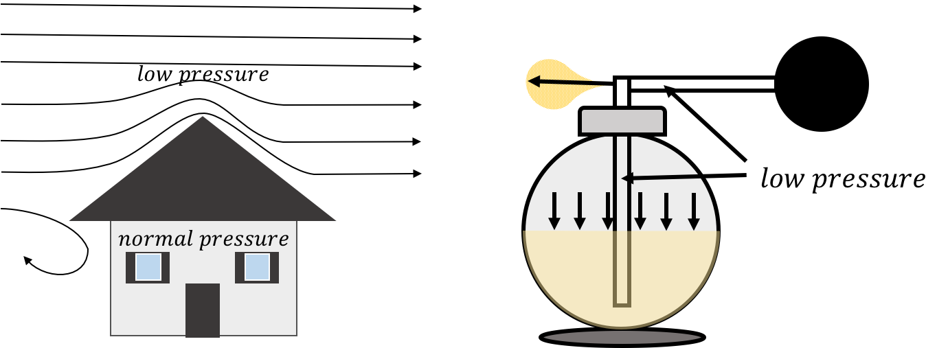
Figure 20:(Left:) the wind flowing above a roof creates a low pressure zone above the roof. (Right:) air flowing above a vertical spout in the atomizer creates a low pressure zone; the air pressure in the bottle forces the liquid up the spout.
The following examples illustrate how to apply Bernoulli’s principle.
14.4.3Viscosity
So far, we have assumed that fluids flow with no friction. In reality, the particles moving in a fluid exert internal friction on each other called “viscosity”. This can be modelled as the friction between different layers of fluid in a laminar flow. For example, you may notice that the water that flows in a wide river flows much faster in the middle of the river than near the river banks, where the water is almost stationary, as shown in Figure 22.
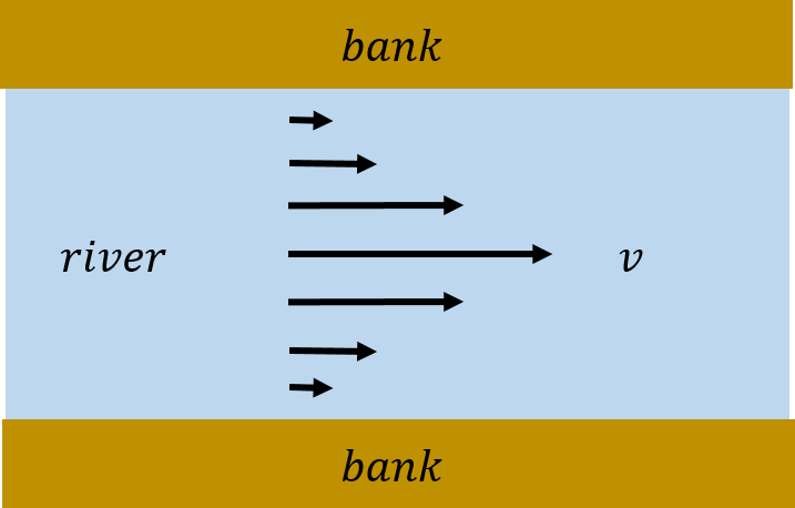
Figure 22:Water flowing in a river; the water near the banks is almost immobile due to the viscosity of the water.
One can model the banks of the river as exerting a frictional force on the layer of water that is in contact with the banks. That layer then exerts a frictional force on the next layer closer to the centre of the river, and so on.
One can define a viscosity coefficient, , based on measuring the force required to pull a plate past another plate when there is a fluid between the plates. Consider two plates that have an area, , that are a distance apart, and contain the fluid of interest between them, as illustrated in Figure 23.
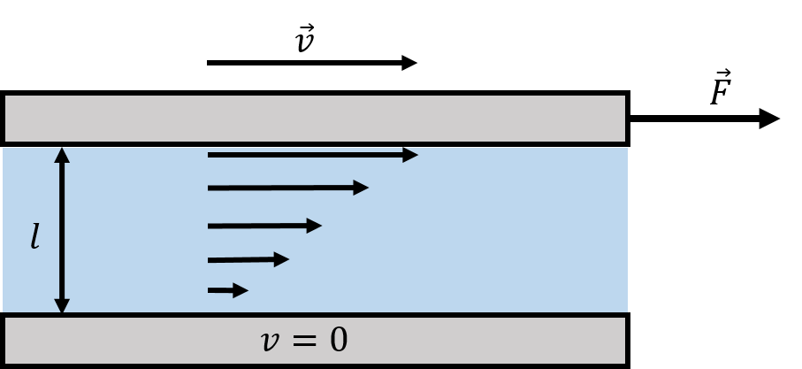
Figure 23:A fluid placed between a moving plate (top) and a fixed plate (bottom) in order to measure the viscosity of the fluid.
The viscosity of the fluid is defined based on the force that is required to pull the top plate while the bottom plate remains immobile. The layer of fluid directly below the moving plate will move with the plate at a speed, , while the layer of fluid immediately in contact will the stationary plate will also be stationary. Moving one plate will thus lead to a gradient (a change) in the speed of the fluid as a function of the position between the two plates. The magnitude of the force, , required to move one plate with speed, , was empirically determined to be proportional to the area of the plates, , and the speed, , while being inversely proportional to the distance, , between the two plates:
The constant of proportionality is defined as the viscosity, , of the fluid:
If the viscosity of the fluid is zero, then no force is required to pull the plate. The more viscous the fluid, the more difficult it is to pull the top plate. You can experiment with this by comparing the force required to move a small piece of paper across the top of a puddle of water and across the top of honey.
The presence of viscosity means that any fluid that flows will lose mechanical energy due to internal friction (which will heat up the fluid). Thus, Bernoulli’s equation is not correct if the fluid has viscosity, as a fluid cannot flow through a horizontal pipe without a change in pressure to overcome the losses due to friction.
14.4.4Poiseuille flow
For the flow of an incompressible viscous fluid through a pipe, one can postulate that the flow rate, , is proportional to the change in pressure, , across the pipe:
where is taken as the positive difference between the pressure at either end of the pipe. The fluid flows from high pressure to low pressure. We can introduce a constant of proportionality, , to be the “resistance of the pipe”, so that we can write:
where we wrote the constant of proportionality as , so that a larger value of corresponds to a pipe with a higher resistance to flow. That is, for a given pressure difference, as one increases the resistance of the pipe, one decreases the flow rate through that pipe. The relationship above can be used to empirically determine the resistance of a pipe.
The flow through a pipe with a given resistance will be zero if there is no pressure gradient in the fluid along the pipe. Conversely, if there is no flow of fluid in the pipe, the pressure is the same everywhere in the pipe. We can thus also view a drop in pressure in a pipe to be the result of flow of liquid through the pipe. The pressure cannot drop across a horizontal pipe if there is no flow.
When you close the tap on your kitchen faucet, the pressure inside the faucet is close to the pressure in the main water line that supplies your house. As soon as you open the tap and allow water to flow, the pressure in your faucet drops to atmospheric pressure, and the resulting pressure gradient from the main supply forces water to flow out of the faucet. If you try to plug your kitchen faucet with your thumb and stop the flow of water, you will need to exert a force large enough to overcome the pressure that exists in the main water supply. You will find that it is practically impossible to stop the flow of water with your thumb, as the pressure in the main supply needs to be high enough to overcome the resistance of the pipes and still result in a usable flow of water.
Poiseuille first developed a model for the laminar flow of a liquid through a uniform horizontal cylindrical pipe of length, , with a circular cross-section with radius . He found that the resistance of such a pipe to a fluid of viscosity, , is given by:
This makes some intuitive sense, as we expect more resistance (more impedance to flow), if the pipe is longer and if the fluid is more viscous (the resistance is zero if there is no viscosity). We further expect less resistance if the pipe has a larger radius. The resistance found by Poiseuille goes down as the fourth power of the radius. Thus, a pipe that is twice as wide will have a volume flow that is times larger because of the reduced resistance.
The laminar flow rate, , of a viscous fluid through a pipe of length and radius , when there is a pressure difference , is given by:
This is usually referred to as “Poiseuille’s Equation”.
14.5Summary
The pressure from a force, , exerted over a surface with area, , is a scalar quantity defined as:
where is the component of the force perpendicular to the surface.
If a force is exerted on the particles in a fluid (e.g. gravity), a pressure will exist everywhere in the fluid. If the fluid is placed in a container, that pressure leads to an external force on all surfaces of the container.
If two fluids at different pressures exist on either side of an interface/object, the net force on that interface/object from the pressures of the fluids will be proportional to the difference in pressure of the fluids on either side.
A fluid is in hydrostatic equilibrium if the sum of the forces on any fluid element is zero. In the presence of gravity, this always leads to a vertical pressure gradient
where is the density of the fluid, is the magnitude of the Earth’s gravitational field, and the axis is positive upwards.
If the fluid is incompressible, then the difference in pressure between two points at heights and is given by:
Pascal’s Principle states that if an external pressure, , is applied to one location in a fluid, then the pressure everywhere in the fluid increases by .
If an object is immersed in a fluid, it will experience a force of buoyancy that is in the opposite direction to the gravitational field in that fluid. The magnitude of the buoyancy force is given by Archimedes’ Principle:
where, , is the density of the fluid and, , is the volume of the fluid displaced by the object (i.e. the volume of the part of the object that is immersed in the fluid).
We can distinguish between laminar and turbulent flow of fluids. In laminar flow, individual particles in the fluid follow well-defined streamlines. In turbulent flow, individual particle follow complicated paths that usually involve Eddy currents. In general, it is much easier to model the laminar flow of fluids.
The equation of continuity states that the mass flow rate of a fluid through a closed system must be the same everywhere in the system (no fluid can appear or disappear). For laminar flow of a fluid with density, , flowing at speed, , through a pipe with cross section, , the mass flow rate is a constant:
A fluid is said to be incompressible if it has constant density. For a fluid of constant density, the volume flow rate, , must be constant everywhere in a closed system:
Bernoulli’s Principle, which is based on the conservation of mechanical energy, states that the following quantity is a constant:
for the laminar flow of a fluid with no viscosity. is the internal pressure of the fluid, its speed, and the height of the fluid relative to a fixed coordinate system. In particular, Bernoulli’s Principle implies that, for a constant height, the internal pressure of a fluid must decrease if its speed increases.
Viscosity, , for the laminar flow of a fluid can be modelled as the result of the internal friction force between layers of the fluid. Because of viscosity, a fluid cannot flow in a horizontal pipe unless there is a difference in pressure across the pipe. Similarly, there will be no horizontal pressure gradient through a fluid unless the fluid is flowing. In general, the volume flow rate, , of an incompressible fluid through a pipe with resistance, , is given by:
For the laminar flow of a fluid with viscosity, , through a horizontal cylindrical pipe of length, , and radius, , the flow rate is given by Poiseuille’s equation:
14.6Thinking about the material
14.7Sample problems and solutions
14.7.1Problems
14.7.2Solutions
Solution 14.1
a. The forces acting on the door are the force of buoyancy, the door’s weight, and the weights of Rebecca and Ryan, as shown in Figure 27.

Figure 27:The forces acting on the door when Rebecca and Ryan are on top of it.
We can combine the weight of the door and the weight of the people into the total weight, . We choose the axis to be positive upwards. The sum of the forces on the door in the direction is given by:
For the door to float, the net force on the door must be greater than or equal to zero. We want to find the minimum buoyant force for them to float, so we set the net force equal to zero:
where the weight includes the mass of Rebecca (), Ryan () and the door (). We added the subscript to the right side of the equation to remind ourselves that the buoyant force depends on the density and volume of the displaced water. We want to find the maximum density of the wood in order for Rebcca and Ryan to stay above the water’s surface. This means that the maximum volume of water that can be displaced is the volume of the door, (so that the surface of the door is level with the surface of the water, as in Figure 25). We can rewrite the mass of the door in terms of its volume and density, and apply our condition that :
A quick calculation tells us that the volume of the door is . We can now calculate the desired density of the wood:
The maximum density of the wood that would allow them to both float is . Balsa wood has a density that is about , so would allow them to survive. However, it is unlikely that a random floating door is made of balsa wood (although one would choose lighter materials when constructing a ship).
b. No, they could not both stay on the door because the density of oak is greater than the maximum density of . We can find the amount of mass that can be added to the door () in order for the person on it to stay above water:
where we again used the condition that . We can plug in the appropriate values and solve:
The door can support an additional mass of , so either Rebecca or Ryan can survive if the other does not get on the door.
Solution 14.2
a. Given that the pressure in the patient’s veins is above atmospheric pressure, we want to find the pressure required at the other end of the needle so that we get the desired flow rate through the needle. We model the needle as a horizontal cylindrical pipe and assume that the saline solution exhibits laminar flow. We can therefore use Poiseuille’s equation:
We let be the pressure where the needle connects to the tube. Solving for gives:
The pressure at the exit of the needle, , is just the blood pressure (). The radius of the needle is . The flow rate has to be in units of . The flow rate in the appropriate units is thus:
Using our values, we can calculate :
Note that, in the first line, we converted into Pascals.
b. We can easily determine the height of the IV bag that is required to give the desired pressure. We choose a coordinate system with a axis that is vertical (positive upwards) with the origin at the location of the needle (Figure 28).
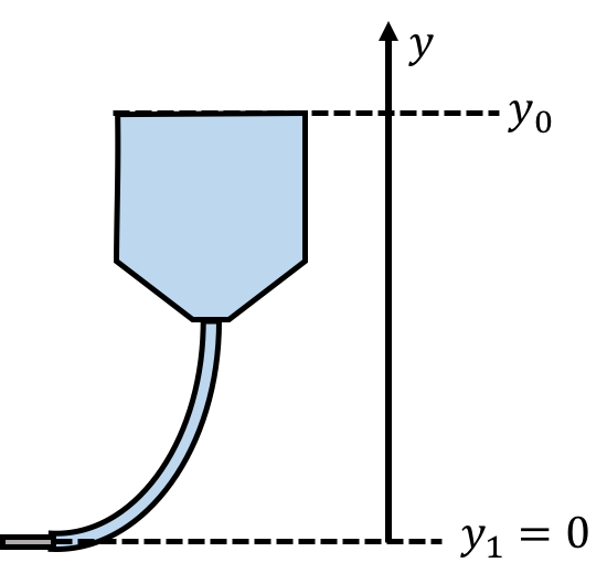
Figure 28:The needle is at height 0 and the top of the fluid in the IV bag is at .
At the top of the solution in the IV bag, , the solution has a speed of zero and is at atmospheric pressure, . The velocity at the needle is 0, and the pressure is . Bernoulli’s principle states:
Using our values to solve for , we get:
Therefore, the IV bag should be placed above the patient’s arm.
We placed the on the top part of the fluid, even though the pressure is higher on the bottom part of the fluid, because the axis increases upwards. We are really interested in the change in pressure, , that corresponds to a change in height, , along the positive direction.
If the velocity of the fluid is not perpendicular to the surface, then is the component of the velocity perpendicular to the surface.